Veress needle with illuminated tip and cavity penetration indicator

a needle and indicator technology, applied in the field ofveress needles, can solve the problems of difficult to see the distal end light source from the exterior of the body, and achieve the effect of improving the penetration rate of the cavity

Inactive Publication Date: 2014-09-16
MOHAJER REZA S
View PDF26 Cites 12 Cited by
  • Summary
  • Abstract
  • Description
  • Claims
  • Application Information

AI Technical Summary

Problems solved by technology

However, in some cases it may be difficult to see the distal end light source from the exterior of the body.

Method used


Image

  • Veress needle with illuminated tip and cavity penetration indicator
  • Veress needle with illuminated tip and cavity penetration indicator
  • Veress needle with illuminated tip and cavity penetration indicator

Examples


Embodiment Construction

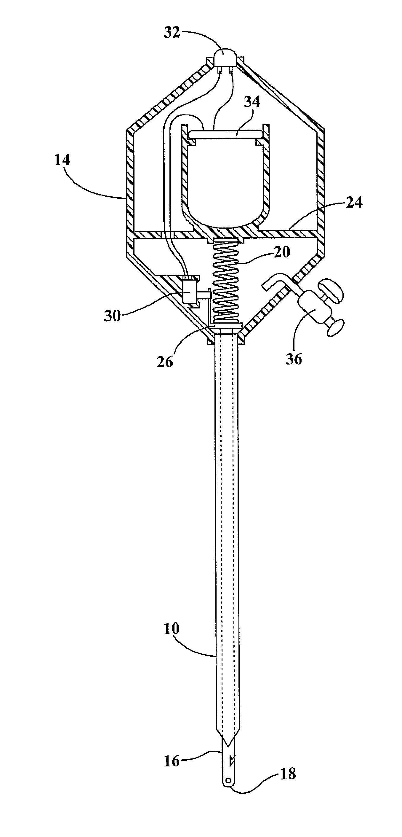
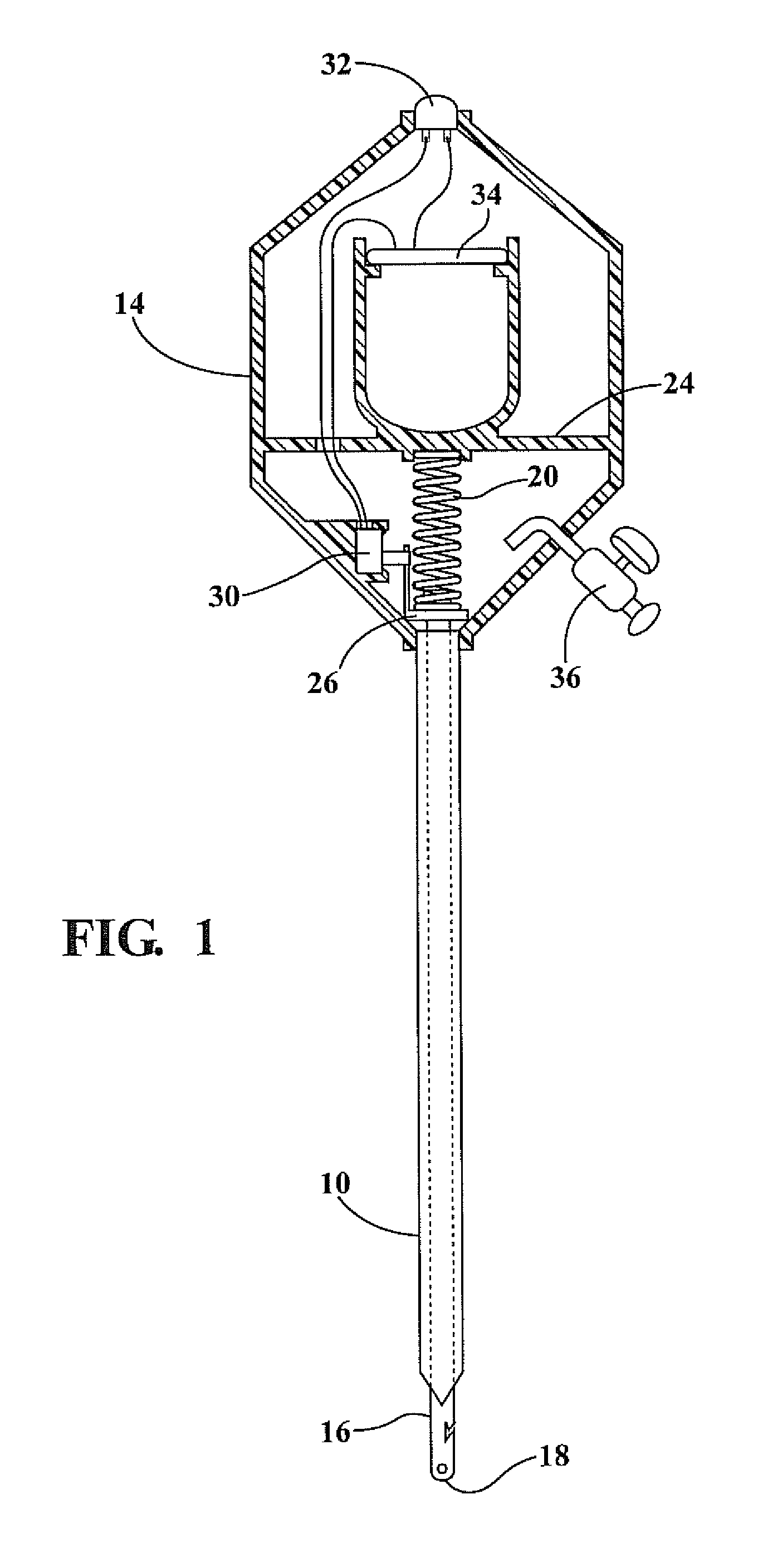
[0012]Referring to FIG. 1, the Veress needle assembly comprising a preferred embodiment of the present invention broadly incorporates an outer cutting tube 10, preferably formed of metal or high-strength plastic, and most preferably formed of stainless steel, having a sharpened distal end 12 used to puncture a hole in the body wall of a cavity during performance of laparoscopic surgery or the like or to cut into other body tissues or organs for the purpose of aspirating fluid from the tissues of these organs. The proximal end of the tube 10 is connected to a handle or housing 14.

[0013]The tube 10 surrounds an inner rod 16 having a blunt distal end 18. The rod end 18 may be simply rounded or may have a crochet suture hook and hole for the purpose of assisting in performing sutures of the incision formed by the outer tube 10 after termination of a process performed by the Veress needle. The rod 16 freely slides within the outer tube 10 and has its upper end within the housing 14 where...


PUM


Abstract

A Veress needle assembly comprises an outer steel tube with a sharpened tip at the distal end surrounding an inner rod having a blunt distal end. The proximal end of the inner rod is spring biased towards a position in which its distal end extends beyond the distal end of the outer stainless steel tube so that while piercing the wall of a body cavity the inner rod is forced upwardly against the spring bias to allow the sharpened end of the outer tube to extend into a cutting position. An indicator light supported on the proximal end of the assembly is controlled by a switch which is in a first position when the outer tube is passing through the wall of the body cavity and a second position when the outer tube enters the body cavity behind the wall, allowing the rod to move beyond the distal end of the outer tube, thereby changing the illumination of the light source so that the operator is signaled that the Veress needle has passed into the body cavity.

Description

CROSS-REFERENCE TO RELATED APPLICATION[0001]This application claims priority of U.S. Provisional Application No. 61 / 360,254 filed Jun. 30, 2010, the contents of which are incorporated herein by reference.FIELD OF THE INVENTION[0002]This invention relates to a Veress needle assembly and more particularly to a Veress needle having a cavity penetration indicator at the proximal end, controlled by the relative positions of an outer steel cutting tube and an interior blunt end rod disposed within the cutting tube.BACKGROUND OF THE INVENTION[0003]In medical practice Veress needles are employed in laparoscopic surgery for penetrating the outer wall of a body cavity for the purpose of insufflation or aspiration of the cavity. Veress needles generally comprise an outer tube, usually formed of stainless steel, having a sharp distal end. An inner rod having a blunt distal end is slidably supported within the outer tube and is spring biased toward extension in the direction of the distal end of...

Claims


Application Information

Patent Timeline
Patent Type & Authority Patents(United States)
IPC IPC(8): A61M5/32A61B17/34A61B5/05A61N1/30A61M5/178A61B19/00
CPCA61B2019/4857A61B17/3474A61B2019/521A61B2090/309A61B2090/0811
Inventor MOHAJER, REZA, S.
Owner MOHAJER REZA S
Why Eureka
Try Eureka