Pivot pin with detent pin installation feature

a technology of installation pin and pivot pin, which is applied in the direction of screws, fastening means, shafts and bearings, etc., can solve the problems of unstable situation, difficult to install the pivot pin in the lower pivot pin aperture of the lower receiver, and the inability to install the detent pin. the effect of easy manipulation by the user

Active Publication Date: 2016-07-26
BATTLEARMS IP LLC
View PDF2 Cites 11 Cited by
  • Summary
  • Abstract
  • Description
  • Claims
  • Application Information

AI Technical Summary

Benefits of technology

[0015]Initial installation requires the rounded portion of the initial end of the pivot pin to contact and maintain an urging force on the rounded or pointed terminal end of the spring biased detent pin. In addition, the detent pin spring, once in the detent pin spring recess, sticks out a few coils. The detent pin has to push on the tip of the detent pin spring and also push back against the rounded side of the pivot pin, resulting in 3 parts and 2 pivot points. The detent pin is not yet in the detent pin spring recess when installation begins, so the detent pin can easily wobble left / right. This creates a very unstable situation, even without spring pressure from the detent pin spring. With the addition of spring pressure, installation of the detent pin is nearly impossible. Therefore, it is not uncommon for detent pins to lose contact with the surface of the pivot pin and be ejected from the detent pin spring recess.
[0018]A redesigned pivot pin would make installation easier and more efficient. Thus, the pivot pin of the present invention includes an initial end that incorporates features that allow a user / operator to use the pivot pin as a tool to install the detent pin more easily without significantly altering the overall size and shape of the pivot pin, when compared to the standard, original pivot pin size. This is a significant difference and improvement over current pivot pin designs.
[0027]The presently disclosed invention separately provides firearm pins that can be easily manipulated by a user.

Problems solved by technology

Unfortunately, it can be quite difficult to initially install the pivot pin in the lower pivot pin apertures of the lower receiver.
This creates a very unstable situation, even without spring pressure from the detent pin spring.
With the addition of spring pressure, installation of the detent pin is nearly impossible.
Unfortunately, many users may not have any such tools unless they routinely install the pivot pins in receivers.
Generally, use of these types of tools is ineffective and can be a hazard to the user's fingers.
Because of the relatively small gap between the lower receiver and the pivot pin and the dimensioning and shape of the various surfaces of known pivot pins and detent pins, it is virtually impossible to use tools or other devices to aid in the installation of the pivot pin.

Method used


Image

  • Pivot pin with detent pin installation feature
  • Pivot pin with detent pin installation feature
  • Pivot pin with detent pin installation feature

Examples


Embodiment Construction

[0056]For simplicity and clarification, the design factors and operating principles of the firearm pins according to this invention are explained with reference to various exemplary embodiments of firearm pins according to this invention. The basic explanation of the design factors and operating principles of the firearm pins is applicable for the understanding, design, and operation of the firearm pins of this invention. It should be appreciated that the firearm pins can be adapted to many applications where two or more components are attached or coupled together using pins.

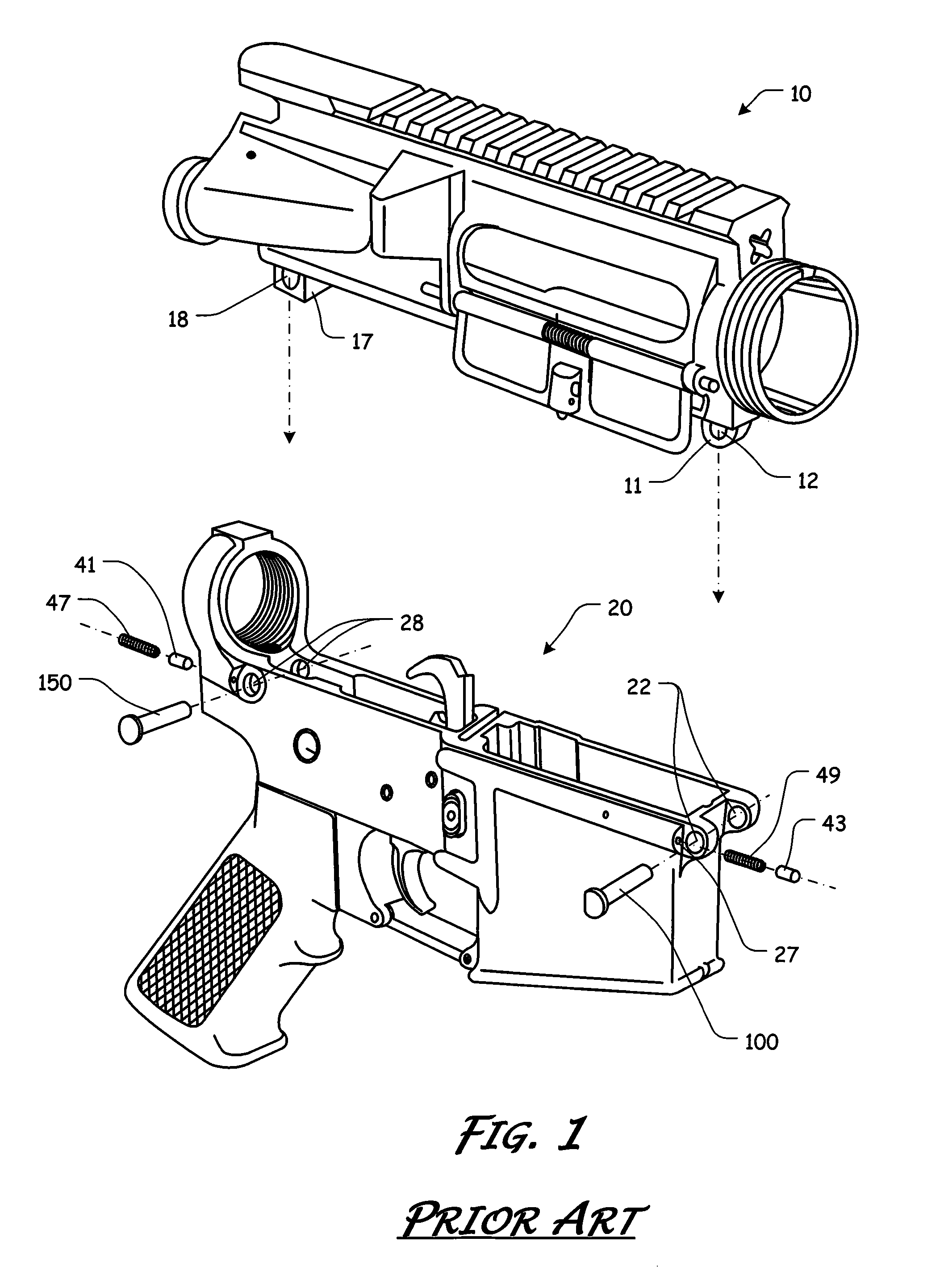
[0057]It should also be appreciated that the terms “AR-15”, “firearm”, “pivot pin”, “pin”, and “firearm pins” are used for basic explanation and understanding of the operation of the systems, methods, and apparatuses of this invention. Therefore, the terms “AR-15”, “firearm”, “pivot pin”, “pin”, and “firearm pins” are not to be construed as limiting the systems, methods, and apparatuses of this invention. Thus, ...


PUM


Abstract

A pin that includes a head and a shank that extends from a shoulder of the head to a terminal surface. A primary channel is formed in a portion of the pin and extends from a portion of the head, along a longitudinal axis of the pin, into a portion of the shank. The primary channel includes a primary recess formed proximate each end of the primary channel. An installation channel is formed in a portion of the pin that extends from a portion of the primary channel, along a longitudinal axis of the pin, towards the terminal surface. The installation channel includes an installation recess formed proximate an end of the installation channel.

Description

CROSS-REFERENCE TO RELATED APPLICATIONS[0001]Not Applicable.STATEMENT REGARDING FEDERALLY SPONSORED RESEARCH OR DEVELOPMENT[0002]Not Applicable.REFERENCE TO SEQUENCE LISTING, A TABLE, OR A COMPUTER PROGRAM LISTING COMPACT DISC APPENDIX[0003]Not Applicable.NOTICE OF COPYRIGHTED MATERIAL[0004]The disclosure of this patent document contains material that is subject to copyright protection. The copyright owner has no objection to the reproduction by anyone of the patent document or the patent disclosure, as it appears in the Patent and Trademark Office patent file or records, but otherwise reserves all copyright rights whatsoever. Unless otherwise noted, all trademarks and service marks identified herein are owned by the applicant.BACKGROUND OF THE INVENTION[0005]1. Field of the Invention[0006]The present disclosure relates generally to the field of installation pins. More specifically, the present invention relates to pins to aid in the assembly and disassembly of various components.[0...

Claims


Application Information

Patent Timeline
Patent Type & Authority Patents(United States)
IPC IPC(8): F16B19/00F16B19/02
CPCF16B19/02F16B21/125F16C11/02
Inventor HUANG, GEORGEWANG, ROGER
Owner BATTLEARMS IP LLC
Why Eureka
Try Eureka