Method and system for managing thermal energy in a building with duct for lifting installations

a technology for building ducts and lifts, applied in ventilation systems, elevators, heating types, etc., can solve problems such as inability to install lifts in low-energy or passive buildings, major thermal losses, and inability to reduce heat losses at ventilation passages, so as to save energy and reduce heat losses of buildings

Inactive Publication Date: 2012-09-11
ROYAL AFC
View PDF12 Cites 2 Cited by
  • Summary
  • Abstract
  • Description
  • Claims
  • Application Information

AI Technical Summary

Benefits of technology

[0011]This method allows to close the ventilation passage and, thereby, to prevent heat losses through the shaft and the ventilation passage. Under certain conditions, the method can therefore meet the requirements of energy-saving by preventing heat loss, whilst always remaining in compliance with legal, technical and safety requirements. Before switching the obturator element to the closed position, the method in fact checks whether the state of the lifting installation allows closing of the ventilation passage. During operation of the lifting installation, the shaft must be ventilated and the obturator element will therefore be kept in its open position. It is clear that the legal and technical requirements take precedence over the thermal energy management requirements and that the obturator element is only switched to a closed position when the legal and technical requirements allow this.
[0012]Furthermore, by preventing heat losses through the ventilation passage of a shaft, the method according to the invention allows installation of a lift in a low-energy or passive building.
[0016]The control unit can conclude that ventilation of the shaft is not necessary, when no presence of a person in the car, on the roof of the car or in the lift shaft is detected; no movement of the car is detected. In this case, it can be deduced that the lifting installation is not being operated. In this case, ventilation of the shaft is not dictated by legal or technical requirements. The obturator element is then free to be switched to its closed position to at least partially obturate the ventilation passage. This can lead to conservation of heat in the building, allowing, amongst other things, installation, until now impossible, of a lift in a low-energy or passive building.
[0018]When no legal or technical requirement prohibits closure of the ventilation passage, the method allows evaluation of the usefulness to close the ventilation passage. The present method allows the obturator element to be switched to its closed position only when such closure is authorized and desired. When closure of the ventilation passage is authorized, thermal energy management of the building is possible by switching the obturator element between its open and closed positions. By closing the ventilation passage, heat losses of the building at the ventilation passage can be reduced, thereby leading to a saving of energy.

Problems solved by technology

In these systems, the ventilation passage is kept closed, which is also contrary to the legal provisions of several countries.
Apart from the legal provisions, there are also economic and ecological issues to be considered.
Any ventilation of the shaft in fact leads to a source of major thermal losses.
Heat loss through the shaft is inevitable, even in the case of simple natural ventilation of this shaft because the doors between the shaft and the different levels of the building can in fact not be airtight throughout the building.
The heat loss is usually so important that installation of a lift in low-energy or passive buildings is in fact made impossible.
However, displacement of the shaft is often undesired or impossible.
However, construction of such an airlock entails very high costs.

Method used


Image

  • Method and system for managing thermal energy in a building with duct for lifting installations
  • Method and system for managing thermal energy in a building with duct for lifting installations

Examples


Embodiment Construction

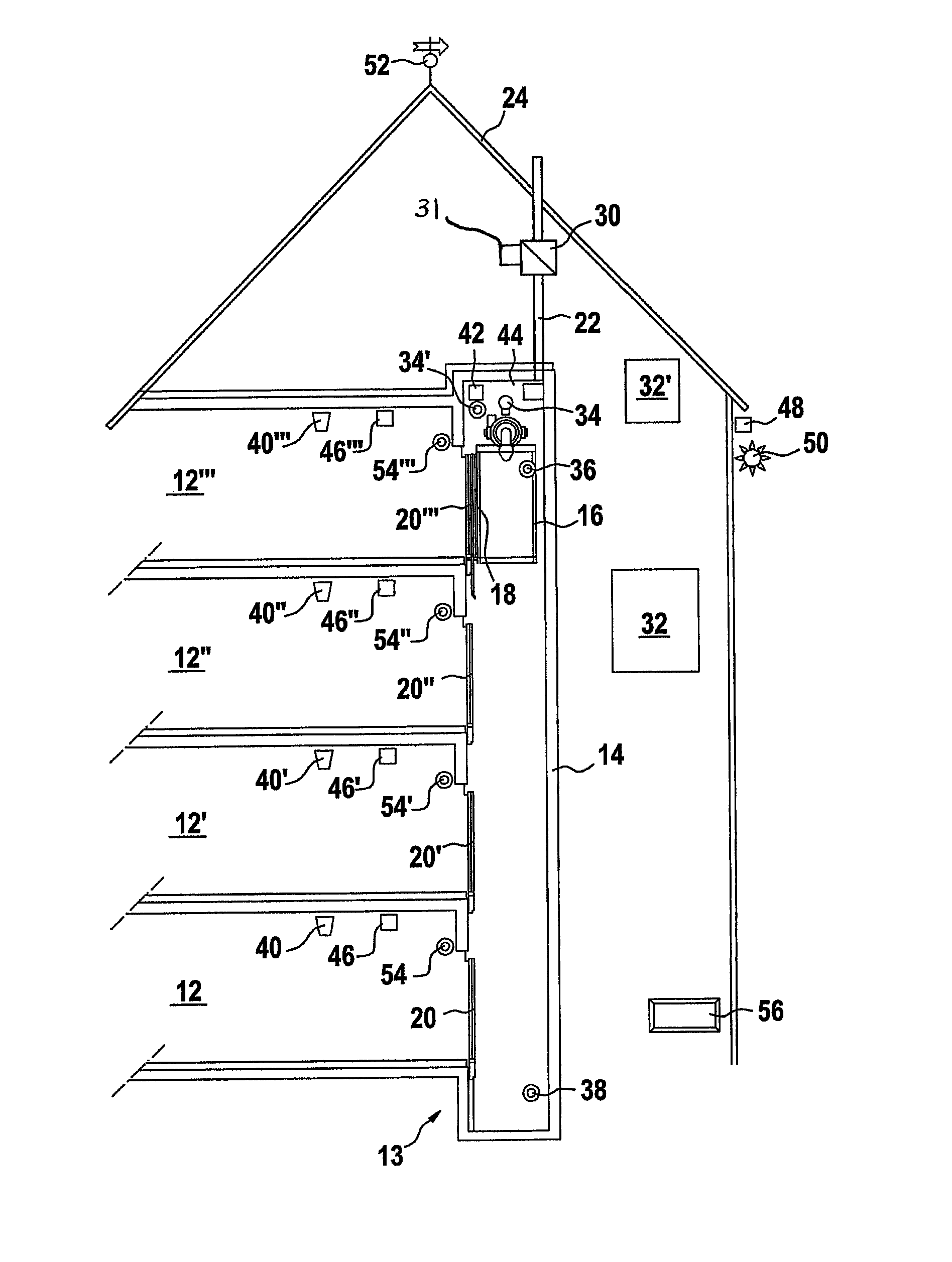
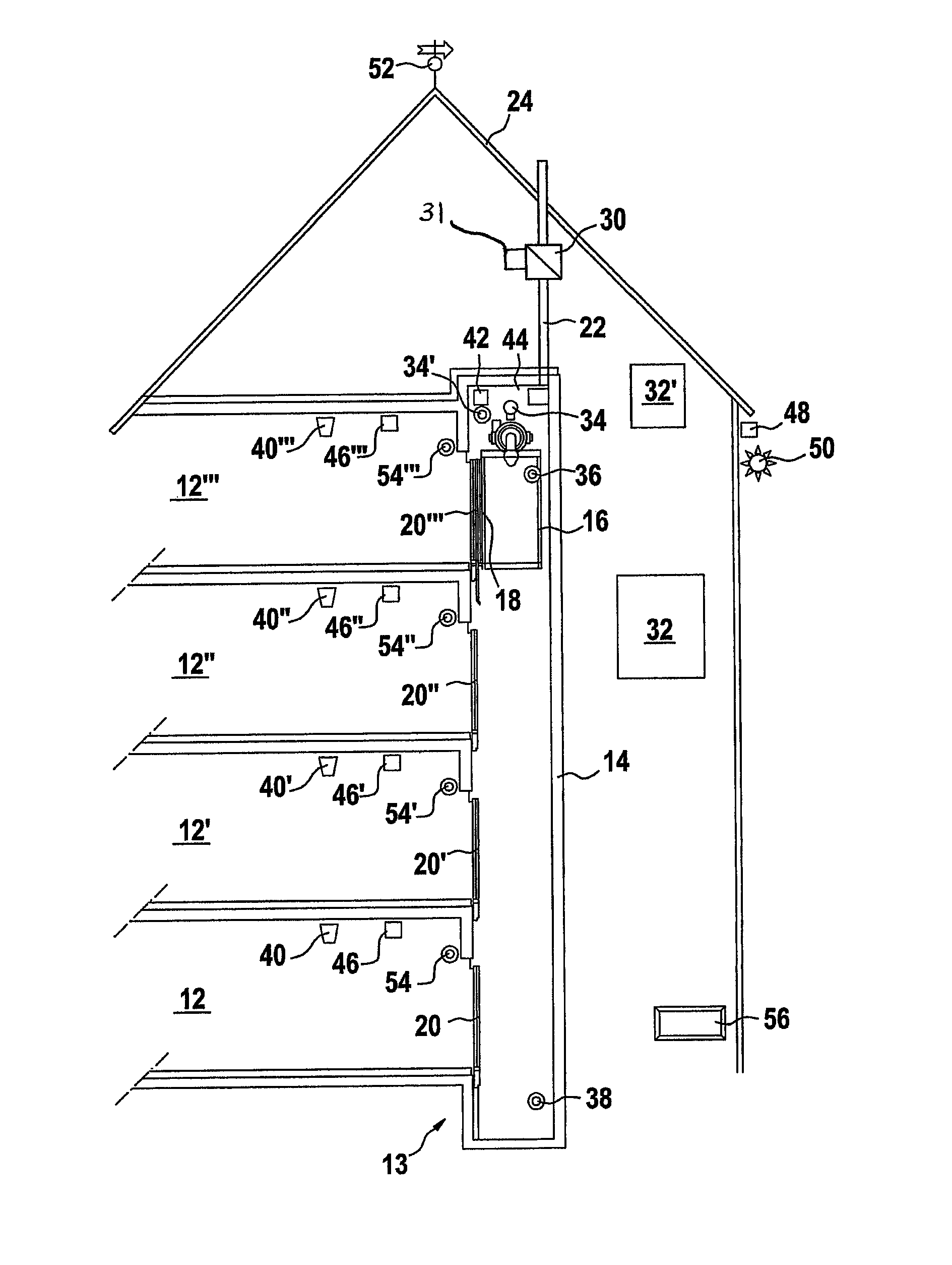
[0025]A building 10 with several levels 12, 12′, 12″, 12′″ is represented in FIG. 1. A lifting installation 13, in this case a lift installation, is vertically arranged in the building 10 to interlink the different levels 12, 12′, 12″, 12′″ of the building 10. Such an installation comprises a shaft 14, wherein is mounted a car 16 connected to a motor (not represented), which makes the car 16 ascend and descend in the shaft 14.

[0026]The car 16 comprises a car door 18, which opens with a respective landing door 20, 20′, 20″, 20′″ at the level 12, 12′, 12″, 12′″, at which the car 16 stops to allow access between the car 16 and the respective level 12, 12′, 12″, 12′″.

[0027]A ventilation passage 22 connects the shaft 14 to the atmosphere through the roof 24 of the building 10. In compliance with European legislations in force, this ventilation passage 22 has a cross-sectional area corresponding to at least 1% of the cross-sectional area of the shaft 14.

[0028]Generally, the car doors 18 a...


PUM


Abstract

The invention concerns an energy management method in a building including a lifting installation with a mobile car in a shaft and a ventilation passage between the shaft and the atmosphere. The method includes the monitoring of at least one state parameter of the lifting installation; the evaluation, in a control unit, of the necessity to ventilate the shaft based on at least one state parameter;the switching of an obturator element associated with the ventilation passage from an open position, wherein the ventilation passages is essentially open, to a closed position, wherein the ventilation passages is at least partially obturated, only when the evaluation indicates that ventilation of the shaft is not required, the obturator element being prestressed in its open position. The invention also concerns an energy management system designed to implement the method according to. The present method and system are particularly suitable for installation of a lift in a low-energy or passive building.

Description

CROSS REFERENCE TO RELATED APPLICATIONS[0001]This application is a continuation under 35 U.S.C. 120 of International Patent Application Ser. No. PCT / EP2006 / 062577 filed on 24 May 2006, and claims the benefit under 35 U.S.C. 119 of Luxembourg Patent Application Serial No. LU 91 175 filed on 13 Jun. 2005, both of said applications are herein incorporated by reference in their entirety.TECHNICAL FIELD OF THE INVENTION[0002]The present invention concerns a thermal energy management, in particular energy-saving, method and system in a building comprising one or more shafts for lifting installations such as, for example, lifts, goods lifts or service lifts, in particular in a low-energy building.BRIEF DESCRIPTION OF RELATED ART[0003]Such a building usually comprises a shaft vertically crossing different levels of the building. For safety reasons, ventilation of the shaft is necessary, for example in the event of a person being trapped in a lift car or in the shaft. Ventilation of the shaf...

Claims


Application Information

Patent Timeline
Patent Type & Authority Patents(United States)
IPC IPC(8): F24F7/00B66B1/34B66B1/06
CPCB66B11/0005F24F7/06F24F11/0001F24F2011/0095F24F11/0034F24F11/30F24F2120/10F24F11/33F24F11/65B66B11/02
Inventor HEIN, CARLOHEIN, MIKE
Owner ROYAL AFC
Why Eureka
Try Eureka