Fuel injector having a nozzle with improved cooling

a fuel injector and nozzle technology, which is applied in the direction of fuel injection apparatus, fuel feed system, engine components, etc., can solve the problems of increasing manufacturing costs, heat deformation of the nozzle tip, and insufficient cooling provided by the fuel flowing through the injector and being sprayed, so as to improve the reliability and performance of the fuel injector, prevent heat transfer, and improve the effect of cooling

Inactive Publication Date: 2006-04-18
CUMMINS INC
View PDF23 Cites 41 Cited by
  • Summary
  • Abstract
  • Description
  • Claims
  • Application Information

AI Technical Summary

Benefits of technology

[0008]Therefore, there exists an unfulfilled need for an improved fuel injector having a nozzle with improved cooling. In particular, there exists an unfulfilled need for such a nozzle that will increase reliability and performance of the fuel injector. In this regard, there is an unfulfilled need for such a nozzle which is sealed to prevent entry of combustion gases to thereby prevent heat transfer from the combustion gases to the nozzle without the disadvantages of the prior art designs, especially when the fuel injector is used for pilot injections or used with alternative fuels.
[0009]In view of the foregoing, it is an object of the present invention to provide an improved fuel injector having a nozzle with improved cooling.
[0010]A second object of the present invention is to provide an improved fuel injector nozzle having increased reliability and performance.
[0011]A third object of the present invention is to provide an improved fuel injector nozzle in which the nozzle is sealed to prevent entry of combustion gases to thereby prevent heat transfer from the combustion gases to the nozzle.
[0012]Yet another object of the present invention is to provide such an improved fuel injector nozzle which will avoid problems of prior art nozzles, especially when the fuel injector is used for pilot injections or used with alternative fuels.
[0013]In accordance with the preferred embodiments of the present invention, these and other objects are obtained by a fuel injector having a nozzle with improved cooling for an internal combustion engine comprising a substantially tubular retainer and a nozzle housing received within the retainer. The retainer has a proximal end with a nozzle support portion, the nozzle support portion having an outer peripheral surface and an engagement opening with an inner peripheral surface. The nozzle housing includes a nozzle shank with a longitudinal axis, an outer peripheral surface and at least one injection hole at a tip of the nozzle shank which is adapted to spray fuel. The nozzle shank is positioned in the nozzle support portion of the retainer. In accordance with this embodiment of the present invention, the outer peripheral surface of the nozzle shank is tapered with respect to the longitudinal axis, and the inner peripheral surface of the nozzle support portion is correspondingly tapered with respect to the longitudinal axis and is sized to engage the outer peripheral surface of the nozzle shank along a tapered interface. In this embodiment, the length of the tapered interface may preferably be greater than a diameter of the nozzle shank. Additionally, the outer peripheral surface of the nozzle shank and the inner peripheral surface of the nozzle support portion may be tapered between 0.5 to 15 degrees. Preferably, in this embodiment, the retainer includes a nozzle sleeve, wherein the nozzle support portion is provided on the nozzle sleeve. The outer peripheral surface of the nozzle shank and the inner peripheral surface of the nozzle support portion are most preferably tapered approximately between 1 to 2 degrees with respect to the longitudinal axis. The fuel injector may be adapted to be received in an injector bore of a cylinder head of the internal combustion engine, and the outer peripheral surface of the nozzle support portion directly contacts either the injector bore of the cylinder head or the coolant jacket sleeve installed in the injector bore.

Problems solved by technology

The present applicants have found that the cooling provided by the fuel flowing through the injector and being sprayed is insufficient to cool the tip of the nozzle.
Consequently, heat deformation of the nozzle tip and fuel coking have been identified by the present applicants as a direct result of insufficient cooling.
However, such alternative fuels have different burn temperatures and characteristics, and certain fuels such as natural gas has a tendency to burn with a combustion flame which is positioned closer to the tip of the nozzle thereby exposing the tip of the nozzle to much higher temperatures than those experienced during normal diesel fuel combustion.
The disadvantage of the invention disclosed in this reference is that it requires a cone having a different material composition than the rest of the injector which may increase manufacturing costs and further complicate the operation of the injector due to the differing expansion and contraction characteristics of the cone as compared to various other components of the injector.
The disadvantage of this design is that it is highly sensitive to manufacturing tolerance variances and is susceptible to failure due to the reduced material thickness of the cylinder head caused by the coolant passage that must flow very close to the nozzle tip.
Therefore, there exists an unfulfilled need for an improved fuel injector having a nozzle with improved cooling.
In particular, there exists an unfulfilled need for such a nozzle that will increase reliability and performance of the fuel injector.
In this regard, there is an unfulfilled need for such a nozzle which is sealed to prevent entry of combustion gases to thereby prevent heat transfer from the combustion gases to the nozzle without the disadvantages of the prior art designs, especially when the fuel injector is used for pilot injections or used with alternative fuels.

Method used


Image

  • Fuel injector having a nozzle with improved cooling
  • Fuel injector having a nozzle with improved cooling
  • Fuel injector having a nozzle with improved cooling

Examples


Embodiment Construction

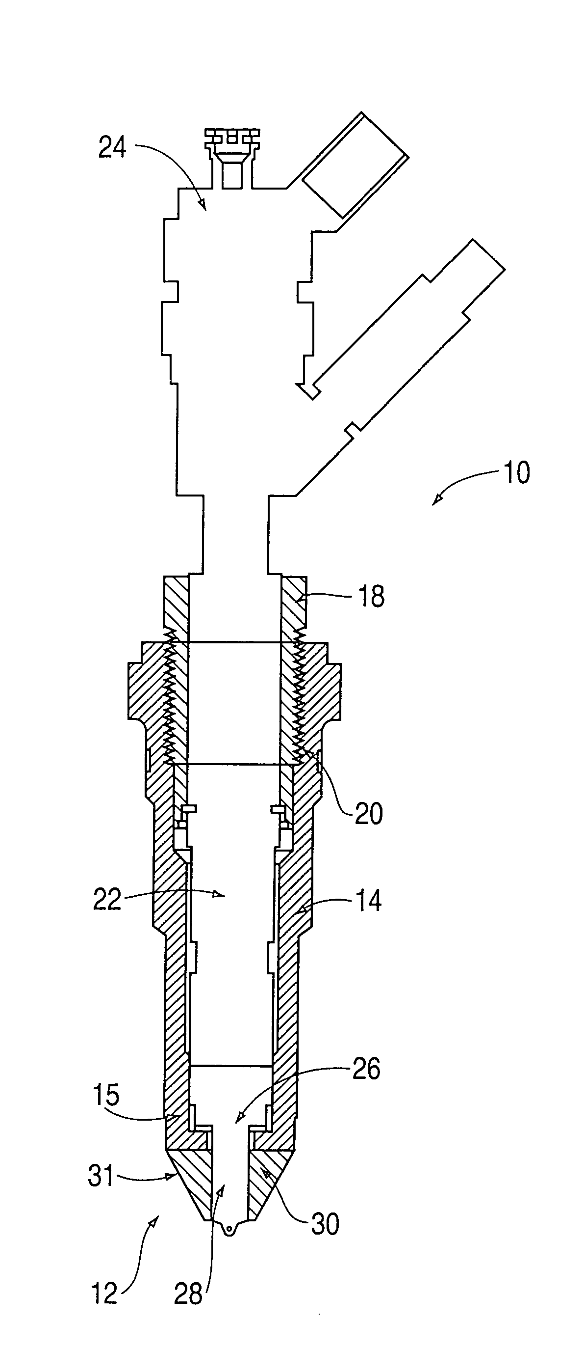
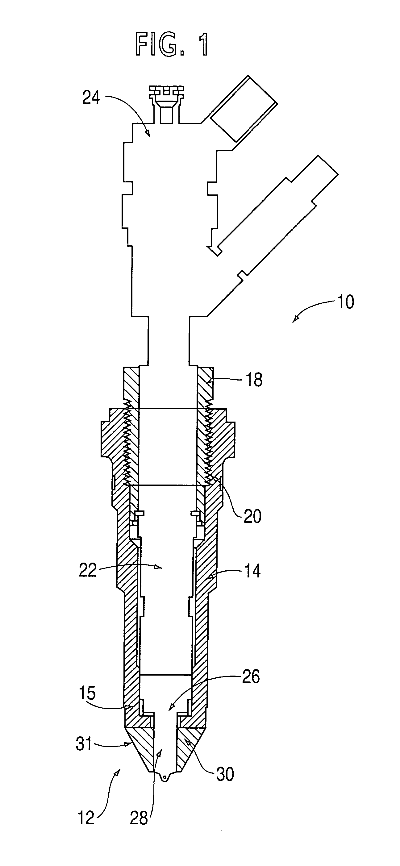
[0025]Various improved fuel injectors are described herein below which have nozzles with improved cooling in accordance with the preferred embodiments of the present invention. As will be evident to one skilled in the art, a fuel injector incorporating the features of the present invention as described below has increased reliability and performance. This is attained by sealing the nozzle from the entry of combustion gases to thereby prevent heat transfer from combustion gases to the nozzle. By practicing the teachings of the present invention, the problems associated with high nozzle temperatures present in prior art fuel injectors can thus be minimized, especially when the injector is used for pilot injections or alternative fuels are used.

[0026]FIG. 1 illustrates a partially schematic and partially cross-sectional view of an improved fuel injector 10 having a nozzle 12 with improved cooling in accordance with one embodiment of the present invention. It should be evident to a pers...


PUM


Abstract

A fuel injector having a nozzle with improved cooling including a retainer and a nozzle housing received therein. The nozzle housing includes a nozzle shank, an outer peripheral surface and at least one injection hole at a tip of the nozzle shank. The nozzle shank is positioned in a nozzle support portion of the retainer. In one embodiment, the outer peripheral surface of the nozzle shank is tapered, and the inner peripheral surface of the nozzle support portion is correspondingly tapered and sized to engage the outer peripheral surface of the nozzle shank along a tapered interface. In another embodiment, the inner peripheral surface of the nozzle support portion has a diameter smaller than a diameter of the outer peripheral surface of the nozzle shank so that an interference fit exists at a seal interface. In yet another embodiment, a nozzle seal seals an interface between the inner peripheral surface of the retainer and the outer peripheral surface of the nozzle shank to thereby prevent entry of hot gases into the interface. In another embodiment, the nozzle support portion is provided on a nozzle sleeve.

Description

BACKGROUND OF THE INVENTION[0001]1. Field of the Invention[0002]The present invention relates to the field of fuel injectors and more specifically, to fuel injectors having a nozzle with improved cooling.[0003]2. Description of Related Art[0004]Fuel injectors have been commonly used with internal combustion engines such as diesel engines to deliver combustible fuel to the combustion chambers within the cylinders of the engine. Various injector designs have been implemented in the art but most fuel injectors have a nozzle with a valve element movably disposed therein in which when opened, provides a spray of fuel into the combustion chamber of the cylinder. In this regard, fuel injectors typically include a nozzle including an outer barrel, a retainer, and a nozzle housing that houses the valve element of the fuel injector. The fuel injector is typically mounted to an injector bore in the cylinder head of the internal combustion engine and the nozzle housing having an injection hole ...

Claims


Application Information

Patent Timeline
Patent Type & Authority Patents(United States)
IPC IPC(8): B05B15/00F02M53/04F02M61/14
CPCF02M61/14F02M53/043F02M2200/858
Inventor BUCHANAN, DAVID L.PETERS, LESTER L.MORRIS, C. EDWARD
Owner CUMMINS INC
Why Eureka
Try Eureka