Liquid crystal display device and method of manufacture of the same
a liquid crystal display and manufacturing method technology, applied in the direction of liquid crystal compositions, instruments, chemistry apparatus and processes, etc., can solve the problems of poor viewing angle characteristics of tn mode liquid crystal display devices, and achieve the effects of good quality, low cost and high reliability
- Summary
- Abstract
- Description
- Claims
- Application Information
AI Technical Summary
Benefits of technology
Problems solved by technology
Method used
Image
Examples
example 1
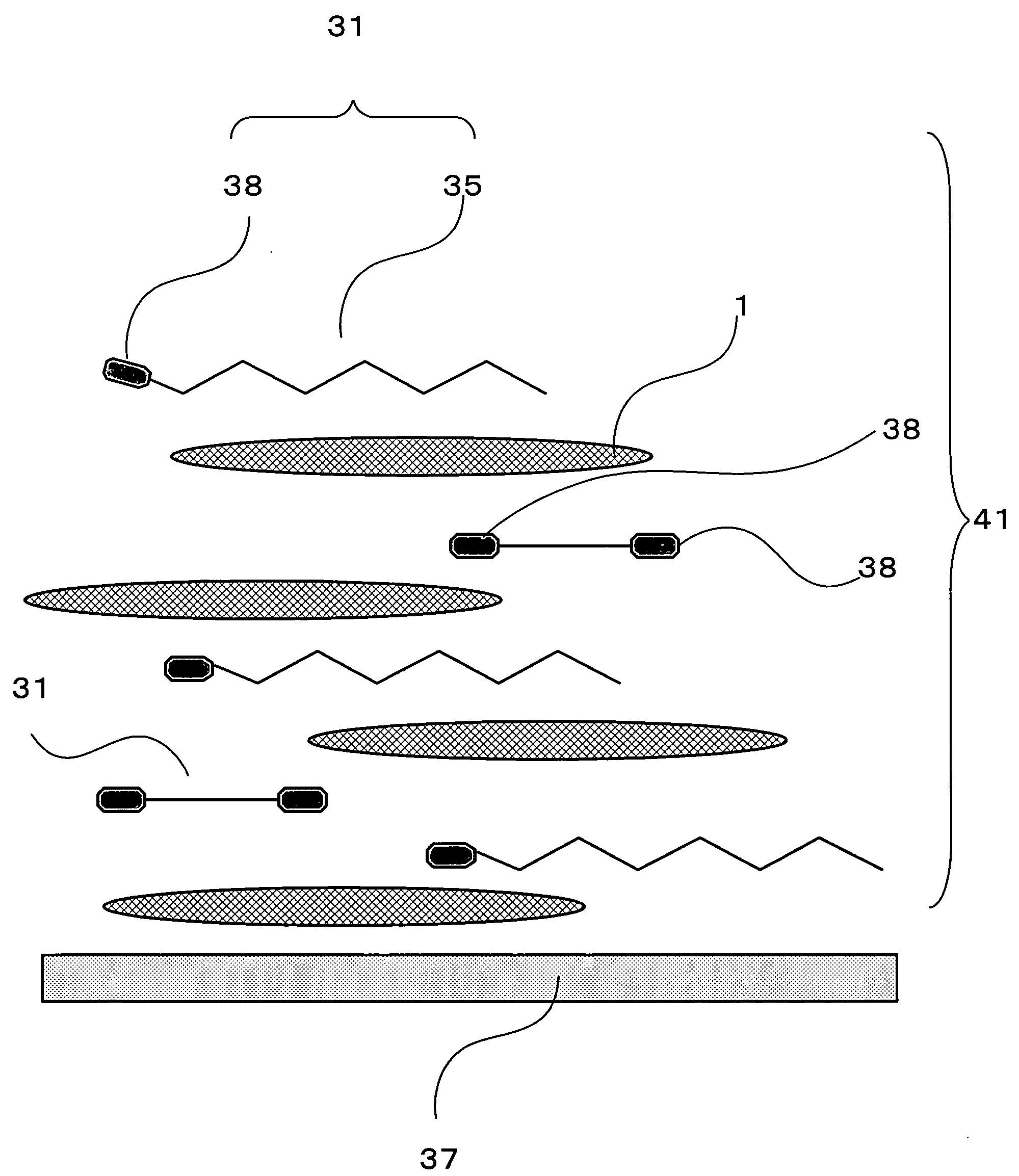
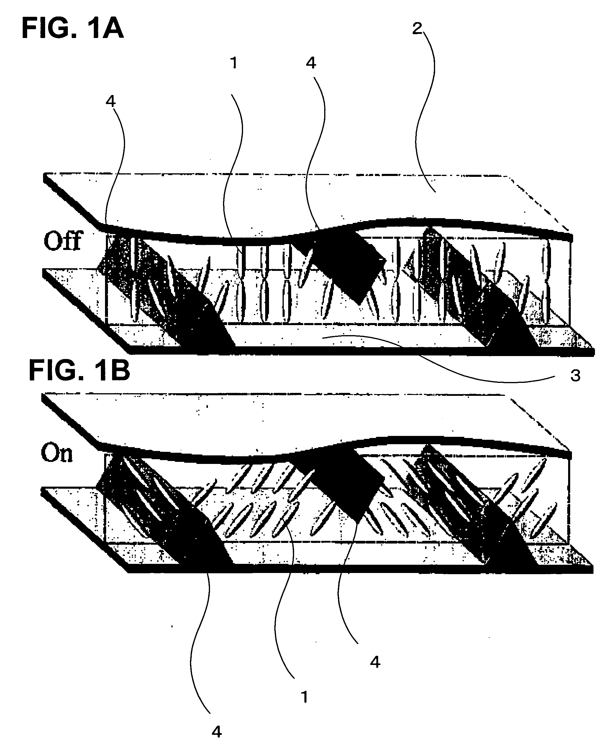
[0061] A monofunctional monomer having an alkyl chain with from 6 to 18 CH2 groups and with an acrylate group, a diacrylate bifunctional monomer having a ring structure, and a polymerization initiator were dissolved in a liquid crystal A produced by Merck & Co. and having a negative dielectric anisotropy to obtain a liquid crystal composition (the weight ratio of monofunctional monomer to bifunctional monomer=10:1). 15-type liquid crystal display panels were prepared by using cells having a thickness of 4.25 μm. Alignment control films were not used. As the monofunctional monomer, each of the five types shown in Table 1 was used.
[0062] Upon observing the alignment state of the liquid crystal display panels immediately after fabrication, nonuniform alignment was observed wherein horizontal and vertical alignments were present together.
[0063] Thereafter, the liquid crystal display panels were subjected to annealing for 30 minutes at 90° C., and after cooling, were irradiated to 9000...
example 2
[0065] In experiments similar to that of EXAMPLE 1, the occurrence of white lines was investigated for a case in which, when the dipole moment vector of a monofunctional monomer was resolved into components in the directions of and normal to the main chain, the main chain direction component was larger than the normal direction component, and for a case in which, when the dipole moment vector of a monofunctional monomer was resolved into components in the directions of and normal to the main chain, the main chain direction component was smaller than the normal direction component. FIG. 5A and FIG. 5B show the occurrence of white lines due to differences in the directions of the dipole moments of monofunctional monomers in the fabricated liquid crystal display panels. FIG. 5A shows a pixel screen of a liquid crystal display panel where the main chain direction component of the dipole moment is approximately ⅕ of the normal direction component, and FIG. 5B shows a pixel screen where t...
example 3
[0067] In experiments similar to those of EXAMPLE 1, the dipole moment of the monofunctional monomer was fixed at approximately 3 debyes, that of a polyfunctional monomer was varied, and the relationship between the reliability and the magnitudes of dipole moment of polyfunctional monomers was investigated. Table 2 shows the relationship between reliability and the magnitudes of the polyfunctional monomer dipole moment. When the dipole moment magnitude was greater than 5 debyes, the reliability was low; when using polyfunctional monomers with a dipole moment at 5 debyes or below, liquid crystal panels with high reliability were obtained.
TABLE 2Relationship between the magnitudes of dipole momentof polyfunctional monomers and the reliabilityMagnitude of dipole momentReliability0.51 debye97.8%1.73 debye97.4%3.04 debye97.5%4.02 debye95.9%5.49 debye88.8%
PUM
| Property | Measurement | Unit |
|---|---|---|
| dipole moment | aaaaa | aaaaa |
| dipole moment | aaaaa | aaaaa |
| voltage | aaaaa | aaaaa |
Abstract
Description
Claims
Application Information
 - R&D
- Intellectual Property
- Life Sciences
- Materials
- Tech Scout
- Unparalleled Data Quality
- Higher Quality Content
- 60% Fewer Hallucinations
Browse by: Latest US Patents, China's latest patents, Technical Efficacy Thesaurus, Application Domain, Technology Topic, Popular Technical Reports.
© 2025 PatSnap. All rights reserved.Legal|Privacy policy|Modern Slavery Act Transparency Statement|Sitemap|About US| Contact US: help@patsnap.com


