
Resonance circuit output characteristic controlling method
A resonant circuit and output characteristic technology, applied in the field of resonant circuit output characteristic control, can solve problems such as weak voltage regulation capability, affecting module performance, and inability to improve control defects.
Patent Information
- Authority / Receiving Office
- CN · China
- Patent Type
- Patents(China)
- Current Assignee / Owner
- Publication Date
- 2008-09-24
Smart Images
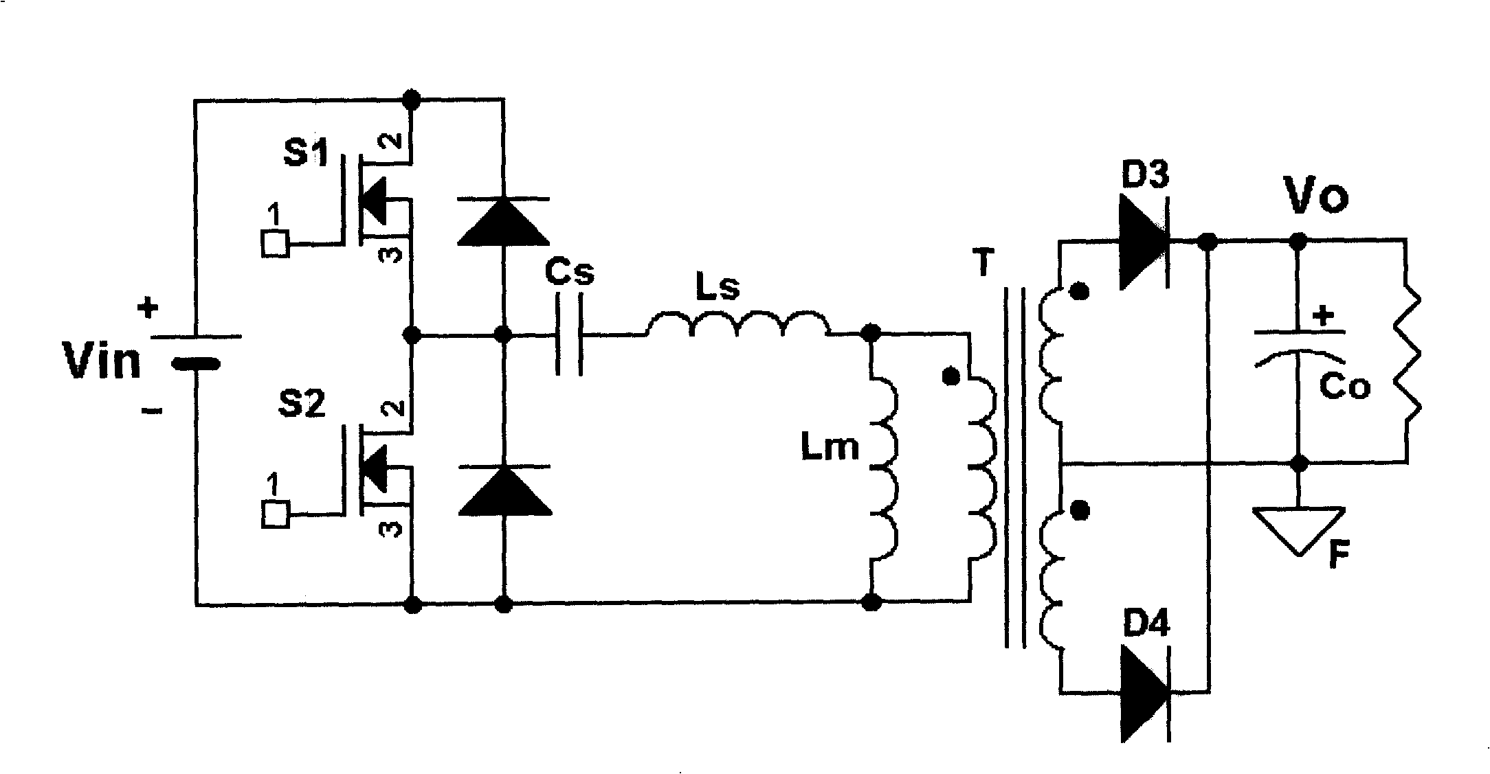
Figure 1 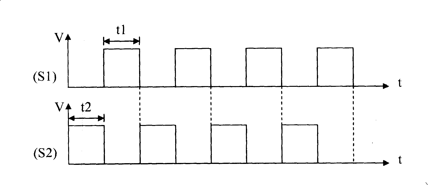
Figure 2 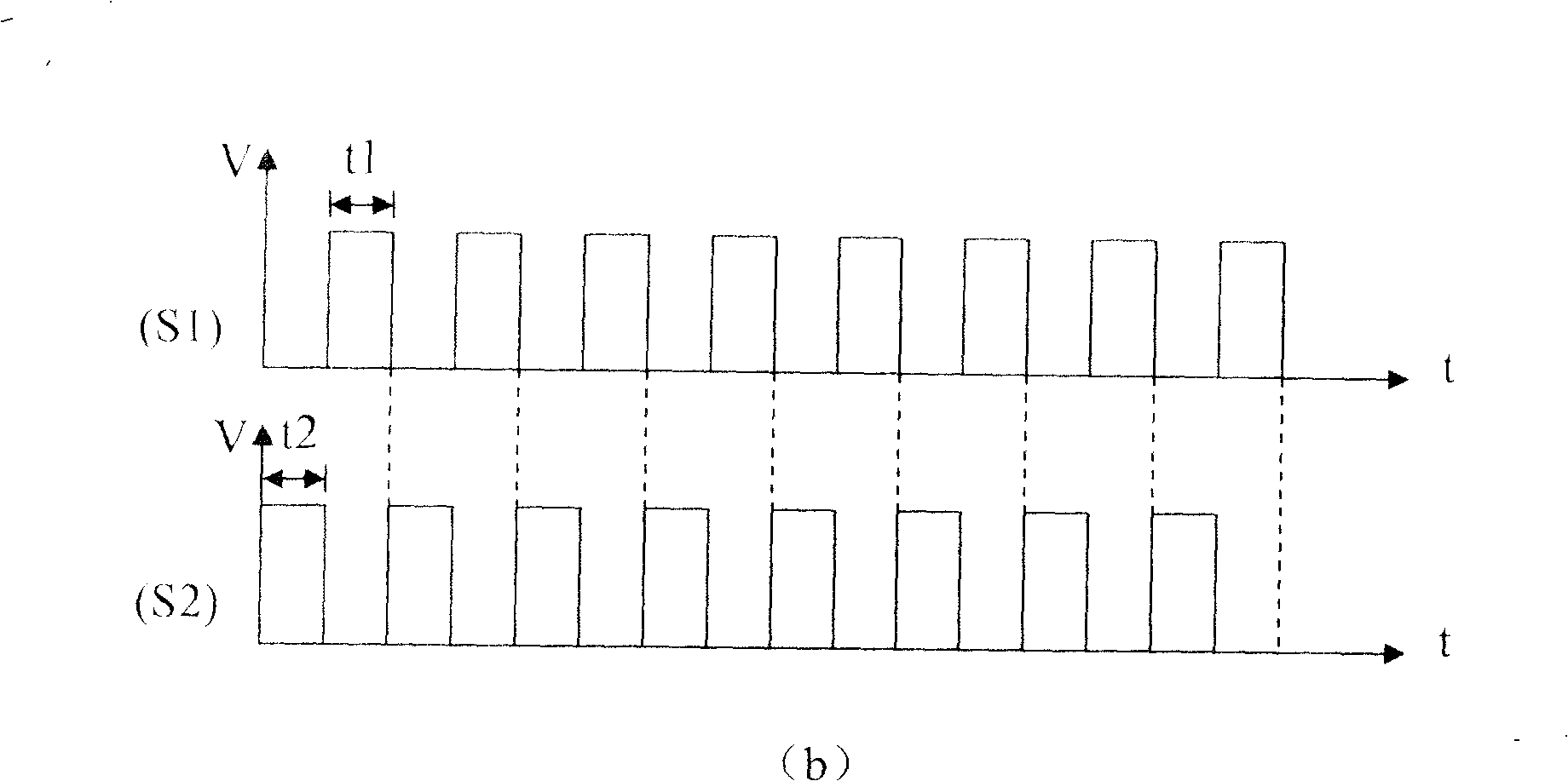
Figure 3
Abstract
Description
Technical field
[0001] The invention relates to a resonant circuit control technology, in particular to a method for controlling output characteristics of a resonant circuit.
Background technique
[0002] At present, the resonant circuit generally adopts a pulse frequency modulation (PFM for short) method, and the required output voltage is obtained by adjusting the switching frequency of the circuit. figure 1 It is a typical half-bridge LLC series resonant circuit, which can realize the zero-voltage turn-on of the main switch tubes S1 and S2, eliminate the reverse recovery of the output rectifier diodes D3 and D4, and improve the efficiency of the circuit. When the circuit is controlled by PFM, the two switching tubes S1 and S2 are driven complementary and symmetrically, and each is turned on for 50% of the switching period. When performing PFM control, the conduction states of S1 and S2 at different frequencies are as follows: figure 2 As shown in (a) and (b), t is ...
Examples
Embodiment Construction
[0019] A method for controlling the output characteristics of a resonant circuit is to adjust the output voltage by comprehensively using PFM and PWM control modes to control two sets of switch tubes of the circuit, so as to improve the control of the voltage output characteristics of the resonant circuit.
[0020] still with figure 1 Take the half-bridge LLC resonant circuit in the example, Figure 4 Curve A in the figure is a schematic diagram of the characteristic curve of output voltage Vo and frequency f with a duty cycle of 50% using a separate PFM control method; Figure 4 Curves B1, B2, and B3 in the figure are schematic diagrams of the characteristic curves of the output voltage Vo and the duty cycle D when the switching frequency is 120kHz, 210kHz, and 290kHz, respectively, using a separate PWM control mode; Figure 4 The curves C1, C2, and C3 in the figure are schematic diagrams of the characteristic curves of output voltage Vo, duty cycle D, and frequency f under ...