

Battery collection instrument and device for preventing collected battery set from short circuit
A technology for battery packs and collectors, which is applied in the direction of measuring devices, overload protection devices, instruments, etc., can solve problems such as battery pack short circuit, switching channel errors, and poor reliability, so as to prevent excessive voltage, improve reliability, and Guaranteed effect
Patent Information
- Authority / Receiving Office
- CN · China
- Patent Type
- Patents(China)
- Current Assignee / Owner
- Publication Date
- 2011-04-06
Smart Images
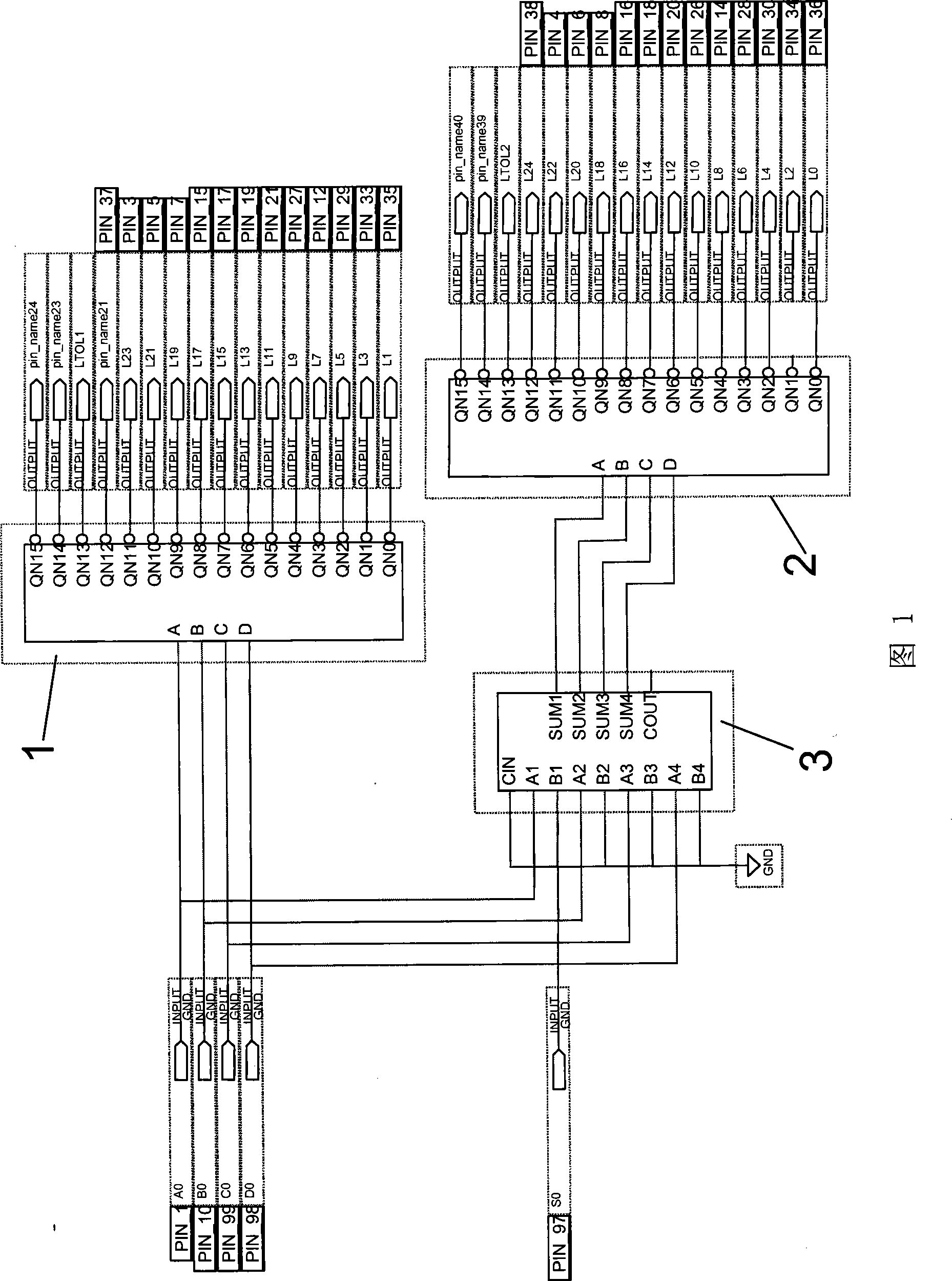
Figure 1 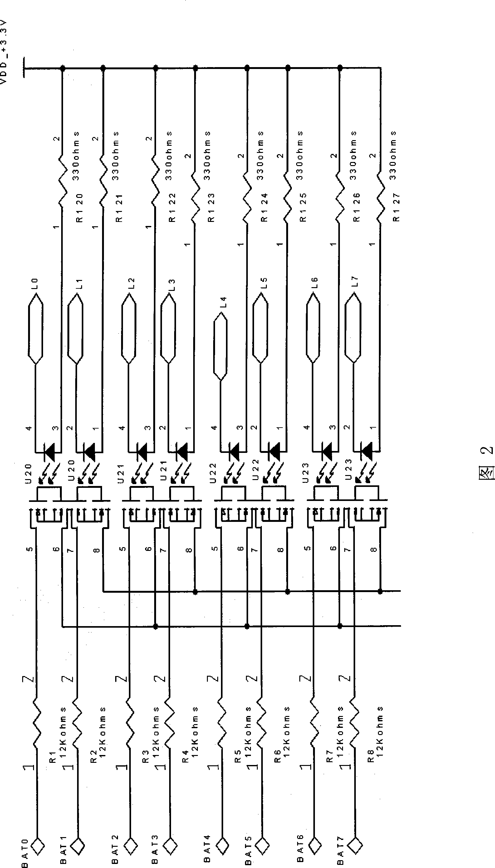
Figure 2 
Figure 3
Abstract
Description
technical field
[0001] The invention relates to a device for preventing short circuit of a battery group collected by a battery collector, and also relates to a battery collector. Background technique
[0002] The internal resistance of battery collectors used in mobile computer rooms and UPSs is very small (less than 1 ohm), which can easily cause short circuits in the battery packs collected by the battery collector. Once the consequences of short circuit are very serious, it will bring heavy losses to customers. At present, battery collectors generally use software to switch channels to prevent battery packs from short-circuiting. However, the reliability of the software is far inferior to that of the hardware, especially when it is disturbed, channel switching errors will occur, resulting in a high voltage input to the battery collector, short-circuiting the battery pack, and damaging the battery collector. The existing method of using software to prevent short circuit...
Examples
Embodiment Construction
[0012] The present invention will be further described in detail below through specific embodiments and in conjunction with the accompanying drawings.
[0013] As shown in FIG. 1 , a device for preventing short circuit of a battery pack collected by a battery collector includes a first decoder 1 , a second decoder 2 and an arithmetic unit 3 . A digital control signal is coupled to the input terminals of the arithmetic unit 3 and the first decoder 1, and the digital control signal is given by a single-chip microcomputer. The output terminal of the arithmetic unit 3 is coupled with the input terminal of the second decoder 2 . The output terminal of the first decoder 1 is coupled to a part of the control channel of the battery pack, and the output terminal of the second decoder 2 is coupled to another control channel of the battery pack; the arithmetic unit 3 is used for digital The control signal is processed so that the control channel where the trigger signal output by the se...