
Intelligent omnibearing health care pillow for treating vertebrae cervicales
An all-round, health-care pillow technology, applied in physical therapy, passive exercise equipment, etc., can solve the problems of lack of effective cervical traction and poor treatment effect, and achieve the effect of relieving pain and promoting blood circulation
Patent Information
- Authority / Receiving Office
- CN · China
- Patent Type
- Patents(China)
- Current Assignee / Owner
- Publication Date
- 2014-02-12
- Estimated Expiration
- Not applicable · inactive patent
Smart Images
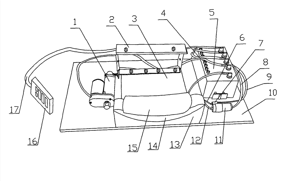
Figure 1 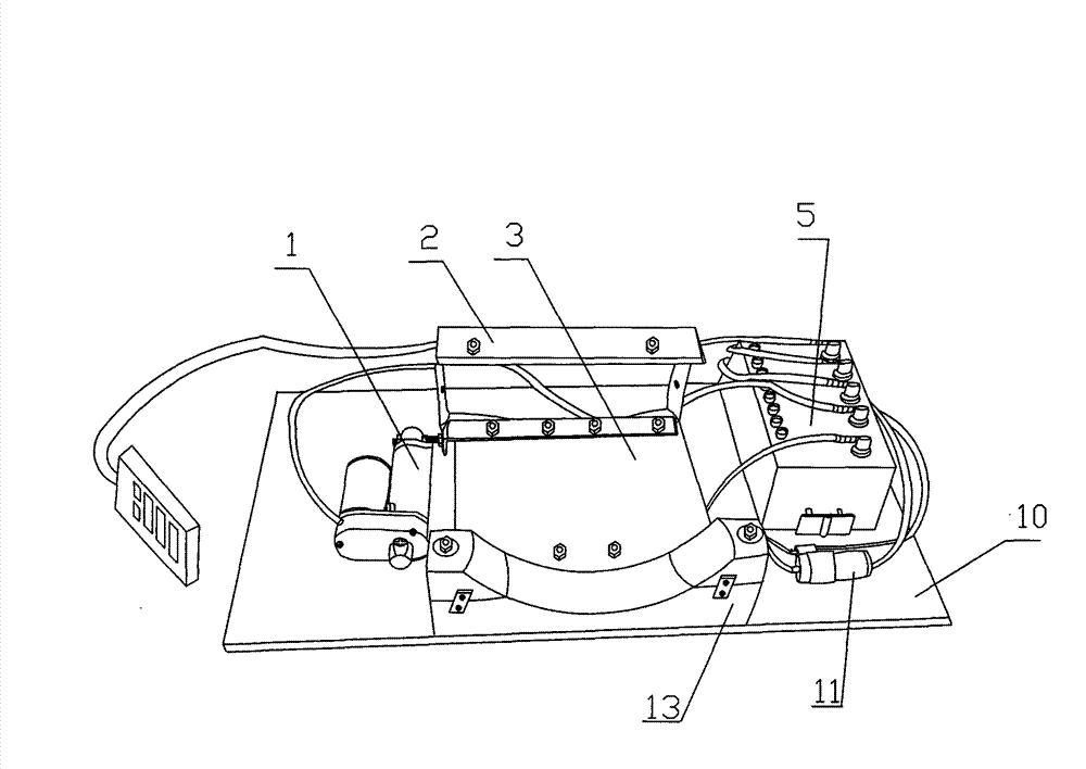
Figure 2 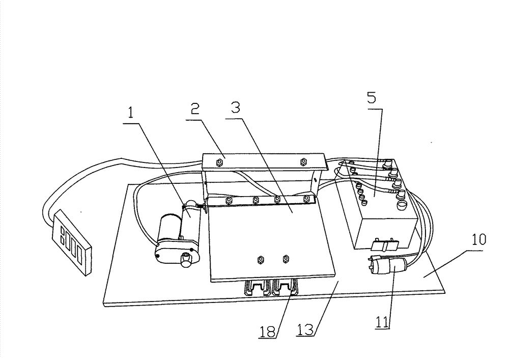
Figure 3
Abstract
Description
technical field
[0001] The invention relates to a health-care pillow for cervical vertebra traction, in particular to an intelligent all-round cervical vertebra treatment health-care pillow. Background technique
[0002] Cervical spondylosis is a disease in which nerves are compressed due to changes in the normal physiological structure (curvature) of the cervical spine, causing pain. The current cervical spine treatment instrument (pillow) is relatively poor in therapeutic effect due to the lack of effective traction to the cervical spine. Contents of the invention
[0003] The purpose of the invention is to develop a kind of intelligent all-round cervical spine treatment health care pillow.
[0004] What the present invention aims to solve is the problem that the existing cervical spine treatment instrument (pillow) lacks effective traction to the cervical spine, making the treatment effect relatively poor.
[0005] In order to achieve the above object, technical schem...
Examples
Embodiment Construction
[0013] The present invention will be further described below in conjunction with the accompanying drawings and embodiments.
[0014] As shown in the figure, the present invention includes a chassis, a tow frame, a remote controller 16 , a control module 5 and a pillowcase 22 . The chassis includes a base plate 10 and a first cover 19 and a second cover 20 fixed on the base plate 10 . A slide rail 18 , an electronic push rod 1 , a control module 5 , an air pump 11 and an air release valve 7 are fixed on the base plate 10 . The bottom of the traction frame is connected with the base plate 10 through the slide rail 18 . The bottom of the traction frame is connected with the electronic push rod 1. An air bag 14 is rested on the traction frame, and the air bag 14 communicates with the air pump 11 and the deflation valve 7 through the air guide tube 12 and the air guide tube 5 respectively. The electronic push rod 1, the air pump 11 and the air release valve 7 are connected to th...