
Feeding mechanism of numerical control turret punch press in X-axis direction
A technology of CNC turret punch press and feeding mechanism, which is applied to feeding devices, metal processing equipment, manufacturing tools, etc., can solve problems such as complicated operation, and achieve the effect of simplifying the mechanical structure, simplifying the structure, and simplifying the structure
Patent Information
- Authority / Receiving Office
- CN · China
- Patent Type
- Patents(China)
- Current Assignee / Owner
- Publication Date
- 2012-08-15
- Estimated Expiration
- Not applicable · inactive patent
Smart Images
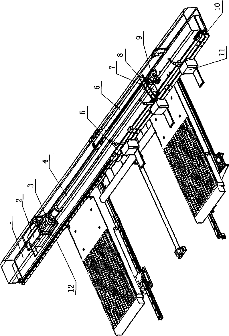
Figure 1 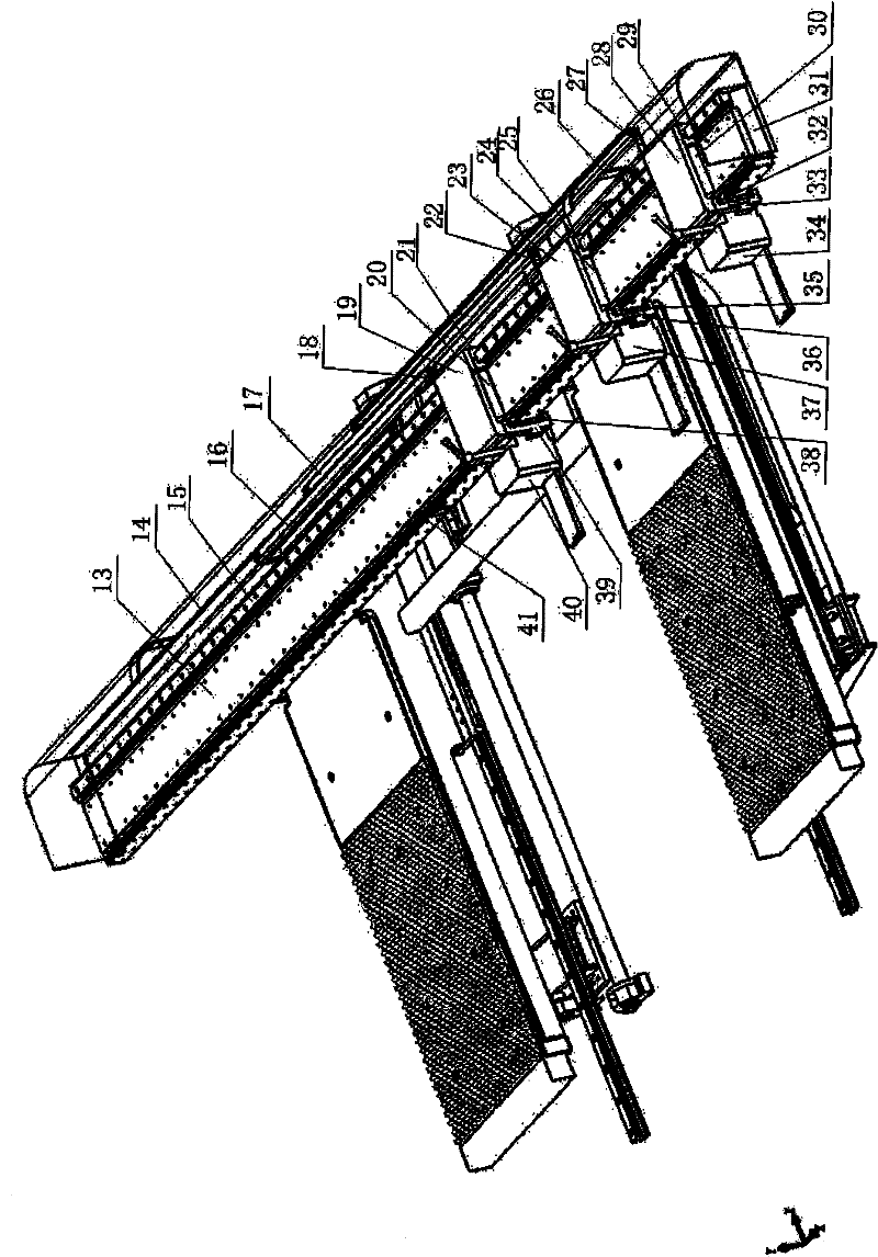
Figure 2 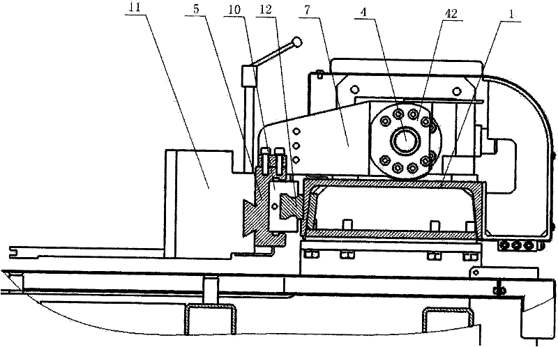
Figure 3
Abstract
Description
technical field
[0001] The invention relates to a numerically controlled turret punching machine, in particular to an X-axis feeding device which is powered by a linear motor and can realize servo positioning of clamps. Background technique
[0002] The CNC turret punch press is the key equipment for sheet metal stamping processing. As a feeding device for automatic feeding of sheet metal, the traditional technology can be found in figure 1 , the motor 2 is used to drive the ball screw 4 to realize the power transmission, and it is guided by the guide rail 12 and the slider 10 . Such as image 3 The shown connecting seat 7 is connected with the lead screw sleeve 42 by screws. On the beam 1, the motor 2 fixed on the motor seat 3 drives the ball screw 4 to rotate. The top of the lead screw 4 moves back and forth along the X direction, the coupling seat 7 and the slide plate 5 are also connected by screws, the slide plate 5 and the slider 10 are connected by screws, and the s...
Examples
Embodiment 1
[0028] Embodiment 1: A turret punch press powered by a linear motor in the X direction feeds components.
[0029] Such as figure 2 , 4 6. As shown in 6: the feeding parts powered by the linear motor in the X direction include beam 31, guide rail I15, guide rail II41, linear motor stator 13, coupling frame I, coupling frame II, coupling frame III, linear motor mover I20, linear motor Motor mover Ⅱ24, linear motor mover Ⅲ30, clamp Ⅰ34, clamp Ⅱ37, clamp Ⅲ40. When the mover of the linear motor moves on the stator of the linear motor, the corresponding coupling frame also moves together under the drive of the mover of the linear motor, thereby realizing the movement of the clamp driven by the coupling frame. Since the wires corresponding to the mover I20 of the linear motor are arranged through the drag chain I16, the wires corresponding to the mover II24 of the linear motor are arranged through the drag chain II17, and the wires corresponding to the mover III30 of the linear mo...
Embodiment 2
[0030] Example 2: Repositioning of Feed Part Grippers Powered by Linear Motors.
[0031] Servo repositioning of the clamp eliminates the need for previously fed parts (such as Figure 5 ) during repositioning, the operation of pressing down the sheet material by the action of two repositioning cylinders 44 on the bed 45 . When one of the three clamps adjusts its position, the other two remain clamped, that is, one clamp releases the sheet, and the position of the linear motor mover on the linear motor stator on the clamp seat plate that is matched with it is adjusted by numerical control , after the clamp is moved to the set position and clamped, a displacement is completed. When repositioning is required, keep the two clamps clamping the sheet, and adjust the displacement of the other clamp. Next, according to the actual situation, you can see how many clamps need to be displaced to achieve clamp repositioning. Through The combined displacement of the clamps by the program ...