
Passive three-balanced frequency converter
A frequency converter, balanced technology, applied in the field of passive three-balanced frequency converter, can solve the problems of reducing the operating frequency range of the diode loop, it is difficult to balance signal transmission and working conditions, and cannot meet the requirements of low-loss frequency conversion, etc., to achieve a simple structure , Good clutter filtering, small footprint
Patent Information
- Authority / Receiving Office
- CN · China
- Patent Type
- Applications(China)
- Current Assignee / Owner
- Publication Date
- 2012-10-03
Smart Images
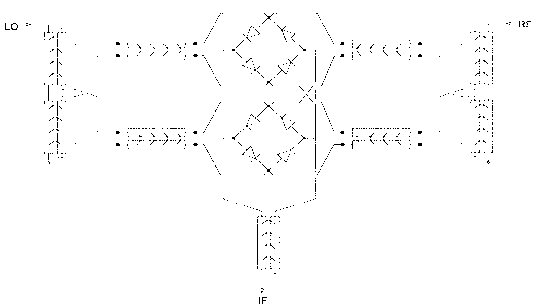
Figure 1 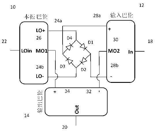
Figure 2 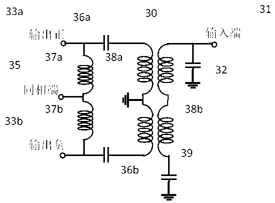
Figure 3
Abstract
Description
technical field
[0001] The invention relates to a passive frequency converter of a radio frequency, microwave, and millimeter wave system, in particular to a passive triple-balanced frequency converter, which can realize frequency conversion between arbitrarily set frequency bands. Background technique
[0002] Passive frequency converters have been widely used in radio frequency, microwave and millimeter wave systems. They are key components of transceiver systems, and are generally used to realize intermediate frequency frequency signals of digital / analog fundamental frequency circuits and radio frequency microwave millimeter waves that can be transmitted wirelessly. An important function of conversion between high-frequency signals such as waves and other frequency bands. However, with the rapid development of wireless communication, the wireless operating bandwidth required by the same transceiver is increasing day by day, and the operating frequency of the intermedi...
Examples
Embodiment Construction
[0022] Such as figure 2, The cathodes and anodes of the four diodes D1, D2, D3, and D4 are connected end to end in turn to form a closed loop. Among the three signal conversion baluns, the local oscillator balun 10 is provided with four ports: an input terminal 22 connected to the local oscillator signal, two balanced differential signal output terminals 24a (LO+) and 24b ( LO-) and an in-phase signal output terminal 26, the in-phase signal output terminal is in the middle position of the two symmetrical balanced differential signal output terminals, according to the required local oscillator frequency and output frequency, it is relative to the two balanced differential signal output terminals. The signal output terminal belongs to the common point MO1 of virtual zero potential. The input balun 12 has four ports: an input terminal 18 connected to the frequency-converted signal, two balanced differential signal output terminals 28a and 28b with the same amplitude but opposit...