
Self-adaptive constant-on-time control circuit
A constant on-time, control circuit technology, applied in the direction of control/regulation systems, electrical components, and adjustment of electrical variables, can solve problems such as changes in operating frequency, achieve frequency concentration, reduce switching actions, and fast load transient response Effect
Patent Information
- Authority / Receiving Office
- CN · China
- Patent Type
- Patents(China)
- Current Assignee / Owner
- Publication Date
- 2015-01-07
- Estimated Expiration
- Not applicable · inactive patent
Smart Images
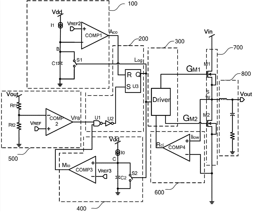
Figure 1 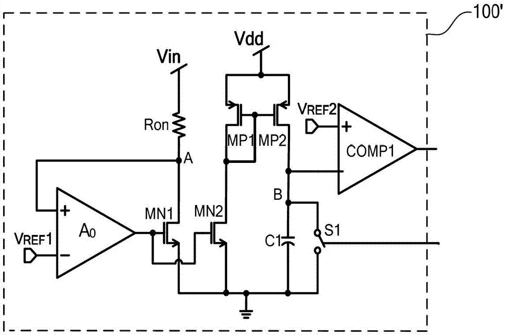
Figure 2 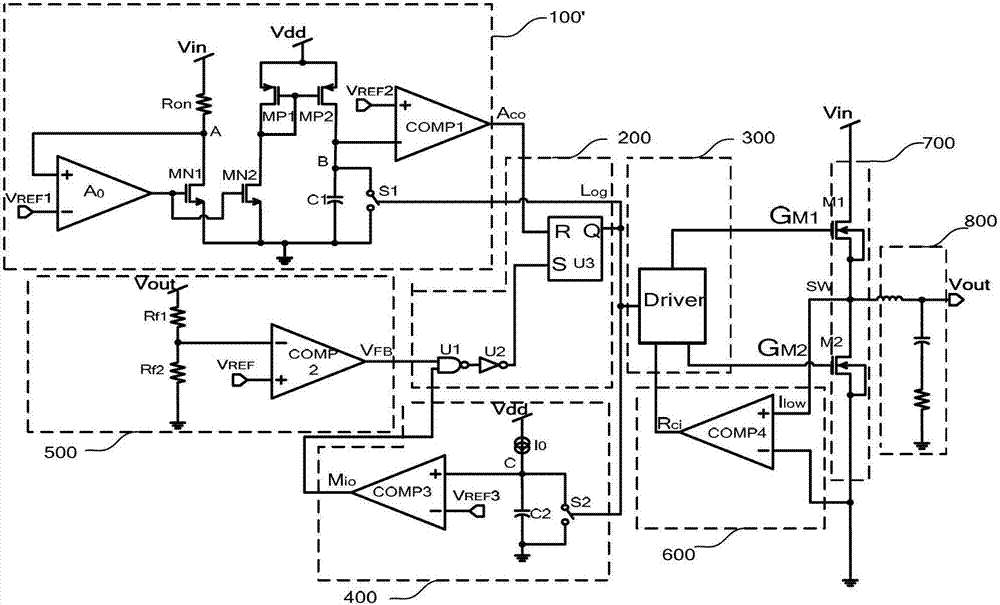
Figure 3
Abstract
Description
technical field
[0001] The invention belongs to the technical field of power supplies, and in particular relates to the design of a conduction time control circuit in a switching regulator. Background technique
[0002] There are many control methods for switching regulators, the most common ones are voltage mode control and current mode control. These two control methods use the error amplifier EA to amplify the difference between the detected output voltage and the reference voltage to adjust the system. The duty cycle D in turn adjusts the output voltage. These two control methods need to add a compensation network to make the system work stably, especially for the current mode control. When the duty cycle D>0.5, an additional slope compensation circuit needs to be added to avoid sub-harmonic oscillation. The addition of these circuits increases the complexity of the control circuit, expands the area of the control chip, and increases the overall cost; at the same t...
Examples
Embodiment Construction
[0030] The present invention will be further described below in conjunction with the accompanying drawings and specific embodiments.
[0031] The structural diagram of the Adaptive constant on time (Acot) control circuit 100' in the embodiment of the present invention is as follows figure 2 As shown, it includes NMOS transistors MN1, MN2, PMOS transistors MP1, MP2, operational amplifier A0, comparator COMP1, capacitor C1, switch unit S1, and resistor Ron. Among them, NMOS transistor MN1, operational amplifier A0, and resistor Ron form a clamping position The op amp fixes the voltage at point A equal to VREF1. The specific connection relationship is that the inverting input terminal of the operational amplifier A0 is connected to the reference voltage VREF1, the gate of the NMOS transistor MN1 is connected to the output of A0, the source and substrate of MN1 are connected to the ground potential, and the drain of MN1 is connected to the high-gain A0. To the input terminal, no...