
Quick solving method on basis of light intensity transfer equation of discrete cosine transform
A technology of discrete cosine transform and light intensity transmission equation, which is applied in the field of fast solution of light intensity transmission equation, can solve problems such as the influence of recovery phase accuracy, low algorithm solution efficiency, difficulty in meeting high-speed, real-time applications, etc., to achieve simple and efficient, Improved accuracy, low external storage effect
Patent Information
- Authority / Receiving Office
- CN · China
- Patent Type
- Applications(China)
- Current Assignee / Owner
- Publication Date
- 2015-02-04
- Estimated Expiration
- Not applicable · inactive patent
Smart Images
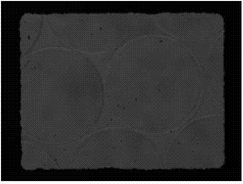
Figure 1 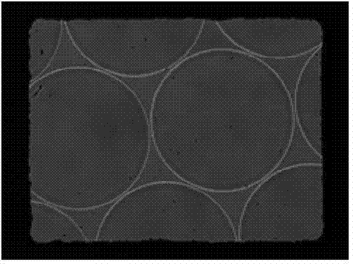
Figure 2 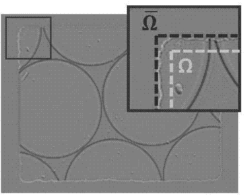
Figure 3
Abstract
Description
technical field
[0001] The invention belongs to phase recovery and quantitative phase imaging technology in optical measurement, in particular to a fast solution method of light intensity transmission equation based on discrete cosine transform. Background technique
[0002] Phase recovery is an important topic in optical measurement and imaging technology, and phase imaging technology is playing an important role in both biomedical and industrial detection fields. Throughout the progress of optical measurement for nearly half a century, the most classic phase measurement method should be none other than interferometry. However, the disadvantages of interferometry are also very obvious: interferometry generally requires a highly coherent light source (such as a laser), which requires a more complex interferometric device; the introduction of an additional reference optical path leads to very harsh requirements for the measurement environment; The speckle coherent noise intr...
Examples
Embodiment
[0063] The experimental results of the present invention on the measurement of micro-optical elements are given below. The sample is a plano-convex quartz microlens array with a pitch of 250 μm (SUSS MicroOptics, lens diameter 240 μm, hexagonal package). In the experiment, the light intensity axial differential signal in the first step It is obtained by using the central finite difference method through two over-focus and under-focus light intensity distributions with a distance of ±550 μm. Figure 1(a) and Figure 1(b) show the collected focused I(r) and out-of-focus (Δz=-550μm) light intensity distribution I - (r). Figure 1(c) is the estimated light intensity axial differential signal The sub-image in the upper right corner is a partially enlarged display of the part in the red frame. Although the shape of the aperture is not an ideal rectangle (limited by the machining accuracy), the boundary signal around the aperture can be clearly observed, corresponding to the In ...