
A high-voltage line robot induction power-taking device and its working method
A technology of inductive power extraction and high-voltage lines, which is applied in the direction of circuit devices, battery circuit devices, collectors, etc., can solve the problems of high work intensity of maintenance personnel, low power fetching voltage, and small theoretical value of induction charging voltage, etc., to achieve guaranteed The effect of taking power output current, increasing power taking output voltage, and increasing power taking output current
Patent Information
- Authority / Receiving Office
- CN · China
- Patent Type
- Patents(China)
- Current Assignee / Owner
- Publication Date
- 2017-03-22
Smart Images
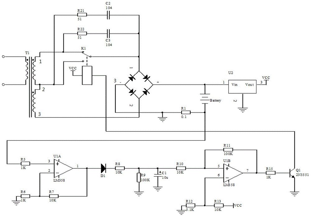
Figure 1
Abstract
Description
technical field
[0001] The invention relates to the technical field of power electronics, in particular to a high-voltage line robot wide-current induction power-taking device and a working method thereof. Background technique
[0002] High-voltage transmission lines are mostly in the form of overhead, across uninhabited mountains, rivers, etc., which brings great difficulties to the maintenance of high-voltage lines. At present, the maintenance work of high-voltage transmission lines mostly adopts the method of manual maintenance. There are many deficiencies in this overhaul method:
[0003] 1. During maintenance, high-voltage lines must be powered off, which will have a great impact on social and economic benefits.
[0004] 2. Maintenance personnel work at heights, and a little carelessness may endanger personal safety.
[0005] 3. The work intensity of maintenance personnel is high.
[0006] Using a robot with a high degree of automation for high-voltage line maintena...
Examples
Embodiment Construction
[0031] The specific implementation manners of the present invention will be further described in detail below in conjunction with the accompanying drawings and embodiments.
[0032] High-voltage line robot wide current induction power-taking device such as figure 1 As shown, it includes a power-taking transformer, a relay, a rectifier bridge circuit, a storage battery, a voltage stabilizer, a current detection circuit and a control circuit; the relay and the rectifier bridge circuit are sequentially connected in series at both ends of the secondary coil of the power-taking transformer, and the rectifier bridge circuit and The accumulator and the voltage stabilizer are respectively connected, the relay is connected with the control circuit, the accumulator is connected with the current detection circuit, and the current detection circuit is connected in series with the control circuit.
[0033] The current detection circuit includes: one end of the sampling resistor R1 is conne...