
Network control-based driver for road lighting LED
A network control and drive technology, applied in the drive field, can solve the problems of insufficient power factor and efficiency, no timing control, dimming control parameter monitoring and data wireless transmission, etc.
Patent Information
- Authority / Receiving Office
- CN · China
- Patent Type
- Applications(China)
- Current Assignee / Owner
- Publication Date
- 2016-04-27
Smart Images
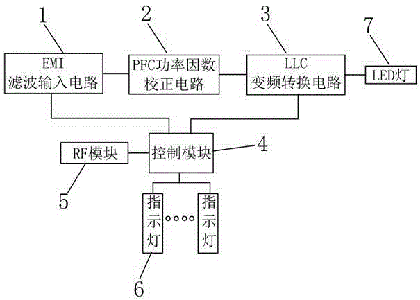
Figure 1 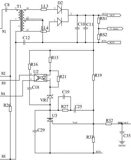
Figure 2 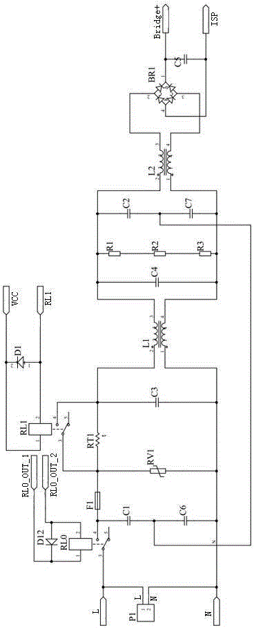
Figure 3
Abstract
Description
technical field
[0001] The invention relates to the technical field of drivers, in particular to a driver for road lighting LEDs based on network control. Background technique
[0002] Lamps using high-power LED light-emitting devices have the characteristics of low power consumption, flexible control, high luminous efficiency, and long life. Currently, they are widely used in urban roads, tunnels, squares, parks, factories and other places that require outdoor lighting. At the same time, LED street lights can be combined with wind power generation equipment, solar power generation equipment and energy storage equipment to form a wind-solar complementary lighting system, further exerting the advantages of green environmental protection, which is of great significance to urban lighting energy saving. In order to meet the needs of urban road lighting, usually a road needs to be equipped with a large number of street lights, which are divided into several light groups according...
Examples
Embodiment
[0025] Embodiment: a kind of driver of road lighting LED based on network control of this embodiment, such as figure 1 As shown, it includes EMI input filter circuit 1, PFC power factor correction circuit 2, LLC frequency conversion conversion circuit 3, control module 4, RF module 5 and several indicator lights 7, and the input end of EMI input filter circuit 1 is connected to the mains , the output end of the EMI input filter circuit 1 is electrically connected to the input end of the PFC power factor correction circuit 2, the output end of the PFC power factor correction circuit 2 is electrically connected to the input end of the LLC frequency conversion conversion circuit 3, and the output of the LLC frequency conversion conversion circuit 3 The terminal is electrically connected to the LED lamp 7, and the control module 4 is electrically connected to the RF module 5, the control terminal of the EMI input filter circuit 1, the control terminal of the LLC frequency conversio...