
Intelligent power cable emergency repair vehicle
A technology for emergency repair vehicles and power cables, which is applied to motor vehicles, vehicle parts, and goods transport vehicles, etc., can solve the problems of low efficiency of communication cable repair operations, high labor intensity of workers, etc., and achieves good mechanical performance, high degree of automation, The effect of easy recycling
Patent Information
- Authority / Receiving Office
- CN · China
- Patent Type
- Patents(China)
- Current Assignee / Owner
- Publication Date
- 2018-05-04
- Estimated Expiration
- Not applicable · inactive patent
Smart Images
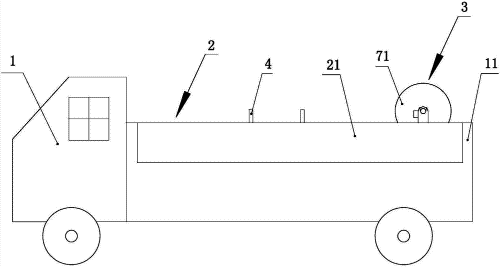
Figure 1 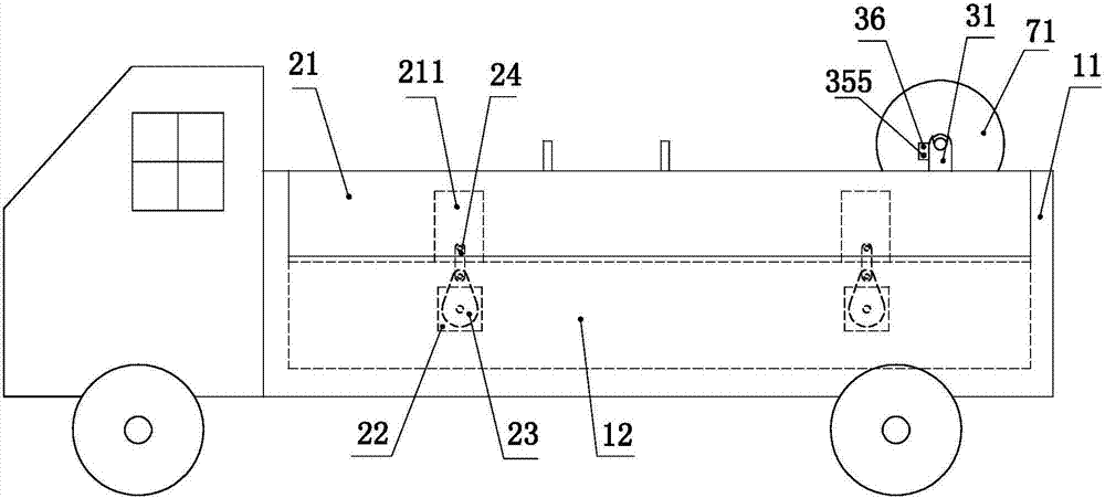
Figure 2 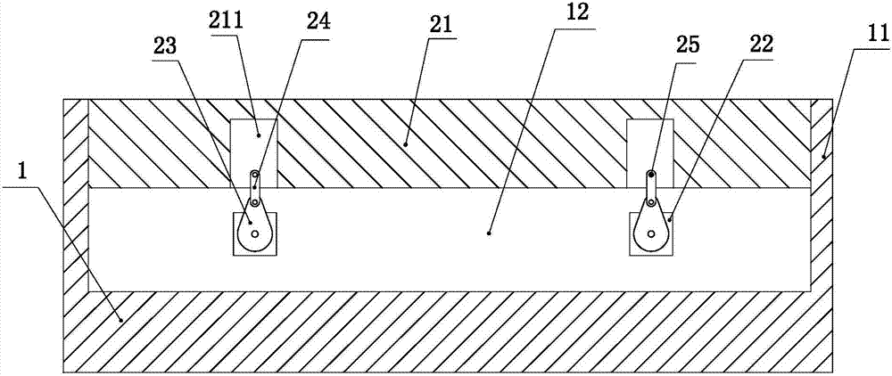
Figure 3
Abstract
Description
technical field
[0001] The invention relates to the technical field of electric power repair, in particular to an intelligent power cable emergency repair vehicle. Background technique
[0002] In the maintenance work of power lines, the maintenance of communication cables is very important. In the existing maintenance and emergency repair of communication cables, people generally climb to a high place by directly climbing to carry out the emergency repair of communication cables. In this process, it is necessary to manually intercept cables, replace electrical components, and recycle old cables. In the above method, the efficiency of the emergency repair operation of the communication cable is low, and the labor intensity of the workers is high. Contents of the invention
[0003] The purpose of the present invention is to provide an intelligent power cable emergency repair vehicle, which is used to improve the working efficiency of the communication cable repair operati...
Examples
Embodiment Construction
[0049] Such as Figure 1 to Figure 21 As shown, the present invention mainly comprises car body 1, side panel assembly 2, new cable handling assembly 3, old cable recovery assembly 4, lifting assembly 5 and length measurement assembly 9, below in conjunction with accompanying drawing to describe the present invention Describe in detail.
[0050] Such as figure 1 As shown, the car body 1 is the base body of the present invention, and the front and rear sides of the car body (based on the orientation when a person sits in the driver's cab) are respectively provided with rails 11, the rails are placed vertically and the front and rear sides of the car body There are two orbits respectively. A side panel assembly 2 is respectively arranged between the two rails on the left side of the car body and between the two rails on the right side of the car body.
[0051] Side panel assembly:
[0052] Such as Figure 2 to Figure 4 As shown, the side panel assembly 2 mainly includes a s...