
Fixture for machining
A kind of machining and fixture technology, which is applied in the direction of manufacturing tools and vises, etc., can solve the problems of damage to the dimensional accuracy of parts and uneven force, and achieve the effect of being conducive to uniformity and force
Patent Information
- Authority / Receiving Office
- CN · China
- Patent Type
- Applications(China)
- Current Assignee / Owner
- Publication Date
- 2016-08-17
- Estimated Expiration
- Not applicable · inactive patent
Smart Images
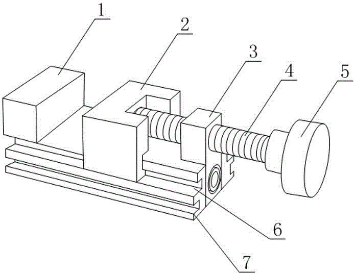
Figure 1
Abstract
Description
technical field
[0001] The invention relates to the field of machining equipment, in particular to a jig for machining. Background technique
[0002] In the process of mechanical manufacturing, the device used to fix the processing object so that it occupies the correct position to accept construction or inspection is generally called a fixture, also known as a jig. In a broad sense, any process in the process of workpiece production, inspection or maintenance, the device used to quickly, conveniently and safely install the workpiece can be called a fixture. Such as welding fixtures, inspection fixtures, assembly fixtures, machine tool fixtures, etc.
[0003] In the prior art, a bench vise is a kind of universal fixture, and is an indispensable clamping device on a fitter's bench. Although the bench vise can clamp larger workpieces and provide sufficient clamping force, for parts with high dimensional accuracy, the bench vise clamp During the holding time, the different p...
Examples
Embodiment 1
[0019] Such as figure 1 As shown, a fixture for machining includes a bottom plate 7, a fixed block 1, a movable block 2 and a pushing device for pushing the movable block 2 to move toward the side of the fixed block 1. The bottom plate 7 is strip-shaped, and the The fixed block 1 is fixed on one end of the base plate 7, the pushing direction of the pushing device is along the length direction of the base plate 7, both sides of the base plate 7 are provided with chute 6 along the length direction of the base plate 7, and the movable card The block 2 is provided with two slide blocks that cooperate with different slide grooves 6 respectively.
[0020] Specifically, in the above structure, by arranging sliders on both sides of the movable block 2, the sliders cooperate with the chute 6, which can be realized in the process of pushing the movable block 2 to the fixed block 1 through the pushing device. , the chute 6 on both sides of the bottom plate 7 conducts wires to the movabl...
Embodiment 2
[0022] The present embodiment is further limited on the basis of embodiment 1, as figure 1 As shown, as a simple implementation form of the pusher, the pusher includes a threaded rod 4, a threaded seat 3 and a handle 5, the threaded seat 3 is fixed on the bottom plate 7, and the threaded rod 4 is threaded with the threaded seat 3 , the axial direction of the threaded rod 4 is parallel to the length direction of the bottom plate 7, the turning handle 5 is fixed on the threaded rod 4, and the movable block 2 is located between the fixed block 1 and the pushing device. In the above structure, during the rotation of the threaded rod 4 , the end of the threaded rod 4 exerts a driving force on the movable block 2 , and the rotating handle 5 is used to drive the threaded rod 4 to rotate.
[0023] As a specific implementation scheme with a loosening function, the threads on the threaded rod 4 and the threaded seat 3 are both fine threads.
[0024] In order to prevent debris from ente...