
Control method, control device and inverter of multilevel inverter
A multi-level inverter and multi-level inverter technology, applied in the direction of output power conversion device, electrical components, AC power input conversion to DC power output, etc., can solve the problem of switch tube breakdown and other problems
Patent Information
- Authority / Receiving Office
- CN · China
- Patent Type
- Patents(China)
- Current Assignee / Owner
- Publication Date
- 2019-05-31
Smart Images
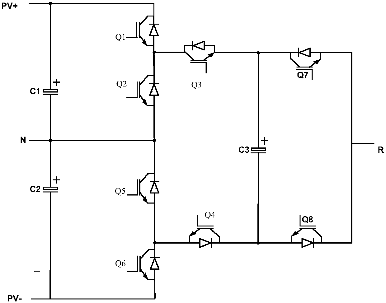
Figure 1 
Figure 2 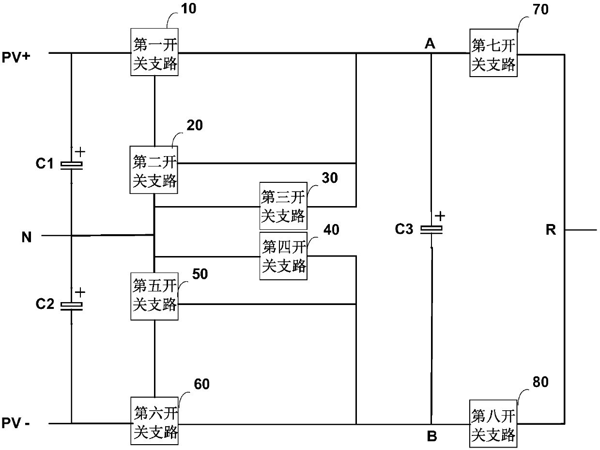
Figure 3
Abstract
Description
technical field
[0001] The invention relates to the technical field of photovoltaic new energy, in particular to a control method, a control device and an inverter of a multi-level inverter. Background technique
[0002] In recent years, multi-level output has become a common technology in the field of medium-high voltage and high-power frequency conversion. Among them, the active neutral point clamping multi-level circuit is a commonly used multi-level inverter circuit, which sets at least one floating capacitor at a certain position of the circuit, so that its level is clamped to form different level output .
[0003] Commonly used five-level inverter circuits such as figure 1 As shown, it includes a plurality of switching tubes and freewheeling diodes, wherein the multiple switching tubes are turned on and off according to a preset logic, thereby realizing the inverter function. Specifically, since the five-level inverter circuit includes three DC capacitors, if some s...
Examples
Embodiment Construction
[0062] In order to make the above objects, features and advantages of the present invention more comprehensible, specific implementations of the present invention will be described in detail below in conjunction with the accompanying drawings.
[0063] The invention provides a control method of a multi-level inverter to solve the problem of breakdown of a switch tube in the prior art when the wave is blocked.
[0064] Specifically, this control method is applied to multi-level inverter circuits, such as image 3 As shown, the five-level inverter circuit includes: a first capacitor C1, a second capacitor C2, a third capacitor C3 and eight switch branches (10-80).
[0065] Specifically, the series branch of the first capacitor C1 and the second capacitor C2 is connected in parallel between the output positive terminal PV+ and the output negative terminal PV- of the DC power supply.
[0066] The first switching branch 10 is connected in series between the first terminal A of the...