
Liquid refractive index sensing method and liquid refractive index sensing device
A liquid refractive index and refractive index technology, which is applied in the measurement of phase influence characteristics, etc., can solve the problems of small dynamic measurement range, variation, and different output characteristics of refractive index sensors, achieve high sensitivity, improve linearity, and expand linearity. The effect of the working area
Patent Information
- Authority / Receiving Office
- CN · China
- Patent Type
- Applications(China)
- Current Assignee / Owner
- Publication Date
- 2017-07-21
Smart Images
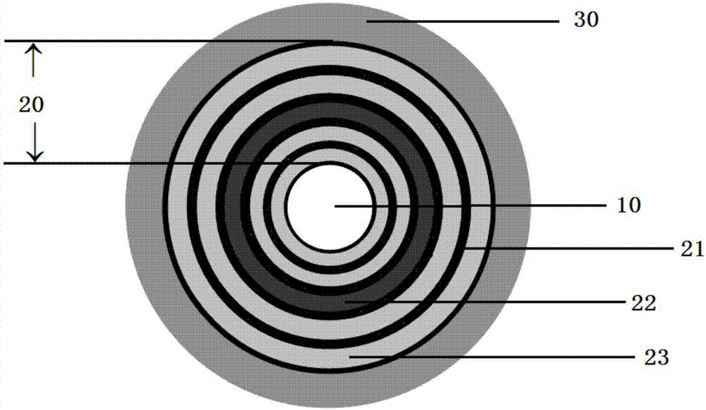
Figure 1 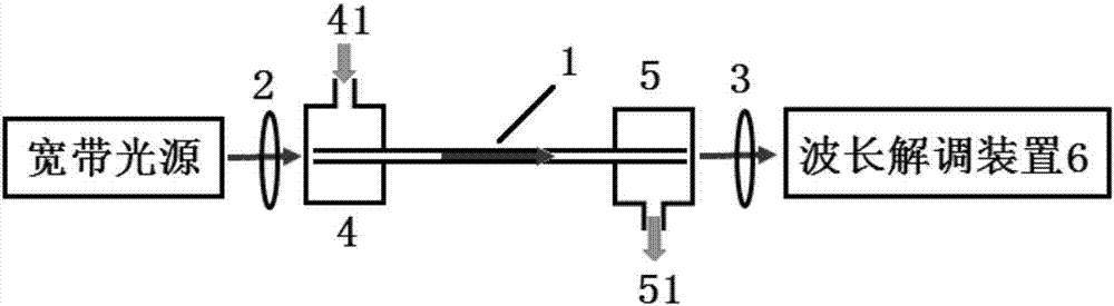
Figure 2 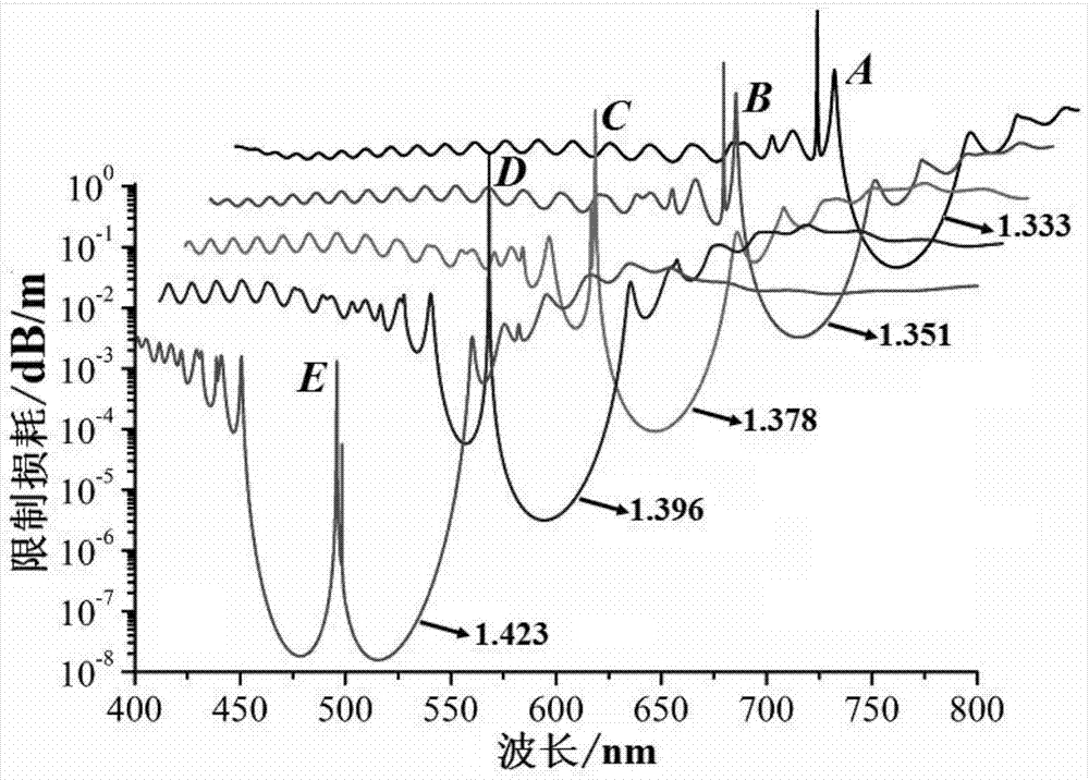
Figure 3
Abstract
Description
technical field
[0001] The invention relates to the technical field of optical fiber sensing, in particular to a liquid refractive index sensing method and a liquid refractive index sensing device. Background technique
[0002] Liquid refractive index measurement has important application value in many aspects closely related to the national economy and people's livelihood, such as environmental water quality monitoring, industrial process control, marine scientific research, food safety testing, and biomedical diagnosis. focus on. In recent years, fiber optic sensor technology has made great progress, and has gradually emerged in many application fields due to its advantages of anti-electromagnetic interference, high sensitivity, compact structure, and easy construction of long-distance and distributed sensor networks. People began to use optical fiber sensing technology to realize remote, real-time and online measurement of liquid refractive index.
[0003] A variety of ...
Examples
Embodiment 1
[0044] image 3 Shown is the structural parameter of the hollow Bragg optical fiber with a defect layer in the refractive index sensing device in Example 1 of the present invention is d c =800μm, N=25, n h =1.581,n l =1.487,n d =1.581,t h =130nm, t l =370nm,t d =1.2t l ,N d = 3, the refractive index of the core filling liquid n a HE at different values 11 Mode confinement loss versus wavelength. Due to the mutual coupling between the defect mode and the core mode, the HE 11 Two loss peaks, one wide and one narrow, appear in the loss spectrum of the mode, and their central wavelengths are respectively denoted by λ RW and lambda RN Indicates that below we will use λ RW (Such as image 3 A, B, C, D and E points in the center) is the characteristic wavelength λ S , to study and analyze its refractive index sensing performance. In Figure 3, A, B, C, D and E correspond to n a The characteristic wavelength λ at 1.333, 1.351, 1.378, 1.396 and 1.423 S . Depend on im...
Embodiment 2
[0045] Embodiment 2: Since the resonance wavelength in the hollow Bragg fiber containing the defect layer depends on the structural parameters of the defect layer, such as the refractive index, thickness and position of the defect layer in the cladding. Therefore, by optimizing the structural parameters of the defect layer, the λ in the liquid-filled hollow Bragg fiber sensor with a defect layer can be further improved S with n a linear correlation between them. Figure 5 The structure parameter of the hollow Bragg fiber with defect layer shown is d c =800μm, N=25, n h =1.581, n l =1.487,n d =1.68,t h =130nm,t l =370nm,t d = t l ,N d= 2, the liquid fills the λ in the hollow Bragg fiber sensor with defect layer S with n a In the figure, the abscissa x represents the liquid refractive index, and the ordinate y represents the characteristic wavelength. to lambda S with n a Linear fitting found that the linear correlation between the two was further improved (R 2 =0...