
ate voltage test system and ate voltage test method
A technology of voltage testing and voltage value, which is applied in the field of display device testing, can solve the problems of IC scrapping, high defective rate, error, etc., achieve good display effect, improve yield rate, and reduce scrapping rate
Patent Information
- Authority / Receiving Office
- CN · China
- Patent Type
- Patents(China)
- Current Assignee / Owner
- Publication Date
- 2019-09-17
Smart Images
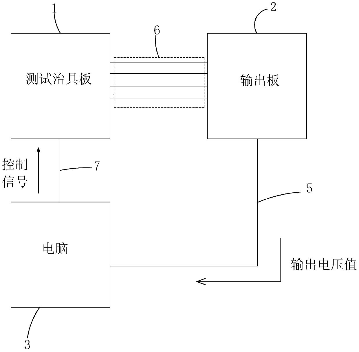
Figure 1 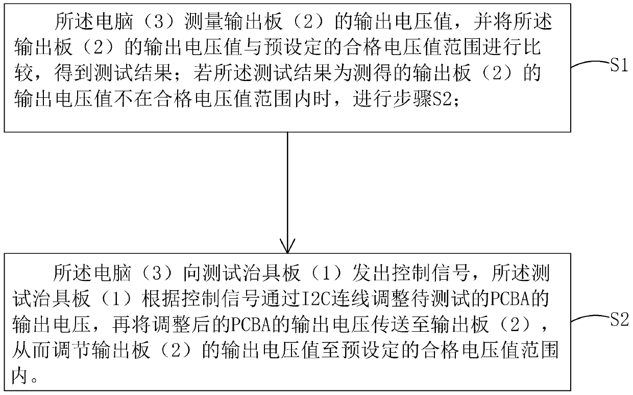
Figure 2
Abstract
Description
technical field
[0001] The invention relates to the field of display device testing, in particular to an ATE voltage testing system and an ATE voltage testing method. Background technique
[0002] In the field of display technology, flat panel display devices such as Liquid Crystal Display (LCD) and Organic Light Emitting Diode (OLED) have gradually replaced Cathode Ray Tube (CRT) displays.
[0003] Most of the liquid crystal displays currently on the market are backlight liquid crystal displays, which include a liquid crystal display panel and a backlight module. The liquid crystal display panel includes a thin film transistor array substrate (ThinFilm Transistor Array Substrate, TFT Array Substrate) and a color filter substrate (ColorFilter, CF) disposed opposite to each other and a liquid crystal layer filled between them. The liquid crystal display includes a plurality of pixels arranged in an array, each pixel is electrically connected to a thin film transistor (TFT), ...
Examples
Embodiment Construction
[0024] In order to further illustrate the technical means adopted by the present invention and its effects, the following describes in detail in conjunction with preferred embodiments of the present invention and accompanying drawings.
[0025] see figure 1 , the present invention provides an ATE voltage testing system, comprising: a test fixture board 1, an output board 2 electrically connected to the test fixture board 1, and electrically connected to the test fixture board 1 and the output board 2 respectively. The computer 3 that is sexually connected; the PCBA to be tested is placed on the test fixture board 1. in:
[0026] The test fixture board 1 is provided with an I2C connection (not shown), for communicating with the PCBA to be tested;
[0027] The computer 3 is used to measure the output voltage value of the output board 2, and compare the output voltage value of the output board 2 with a preset qualified voltage value range to obtain a test result; The above tes...