
Three-dimensional non-orthogonal tracking and scanning test head calibrating method
A technology of scanning probe and calibration method, which is applied in the direction of measuring devices, instruments, etc., can solve the problems of not being able to reflect the working conditions of the internal sensors of the three-dimensional non-orthogonal tracking scanning probe, adverse effects on accuracy, and large calibration errors.
Patent Information
- Authority / Receiving Office
- CN · China
- Patent Type
- Applications(China)
- Current Assignee / Owner
- Publication Date
- 2018-09-28
Smart Images
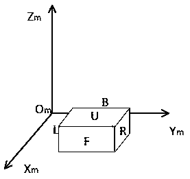
Figure 1 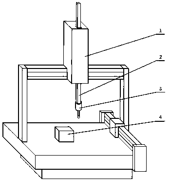
Figure 2 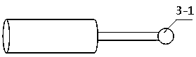
Figure 3
Abstract
Description
technical field
[0001] The invention belongs to the field of precision testing technology, instruments and precision machinery, in particular to a three-dimensional non-orthogonal tracking scanning probe calibration method based on a coordinate measuring machine. Background technique
[0002] In manufacturing and processing, accurate and timely acquisition of characteristic information of the measured object can improve processing accuracy, improve part manufacturing efficiency, and reduce production costs. Measurement technology has become an important technology in the industrial field. At present, the detection methods of parts in the industrial field can be divided into two categories: contact and non-contact. Non-contact measurement such as laser measurement, structured light vision measurement, etc., has a high efficiency of information acquisition, and the accuracy is better in the laboratory environment, but in actual use, its measurement accuracy and stability are v...
Examples
Embodiment Construction
[0033] Step 1 Install the standard measuring cube Q ,Such as figure 1 shown, and operate a CMM using a variety of methods such as a calibrated touch probe or optical scanning to ensure its left L with front surface F machine coordinate axis , machine tool coordinate axis parallel, and read out its mounting coordinates, including: its front surface F , back surface B Corresponding machine coordinate axis coordinate value , left side L , right side R Corresponding machine coordinate axis coordinate value , on top U Corresponding machine coordinate axis Axis coordinate value . CMM C Install a three-dimensional non-orthogonal tracking scanning probe on the z-axis P (hereinafter referred to as the probe P ),Such as figure 2 shown.
[0034] Step 2 Jog to control the three-coordinate measuring machine C drive probe P move so that the probe P ball finger I (Such as image 3 shown) with standard measuring cubes Q the front surface of F contact, such ...