
Air-conditioning system, method and device for measuring refrigerant weight of air-conditioning system
An air-conditioning system and refrigerant technology, applied in the direction of machinery and equipment, can solve the problems that cannot be quantified, the estimation results are vague, and cannot provide more detailed support and help, and achieve the effect of ingenious structure, simple calculation, and prevention of after-sales problems
Patent Information
- Authority / Receiving Office
- CN · China
- Patent Type
- Patents(China)
- Current Assignee / Owner
- Publication Date
- 2020-07-24
Smart Images
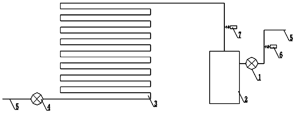
Figure 1 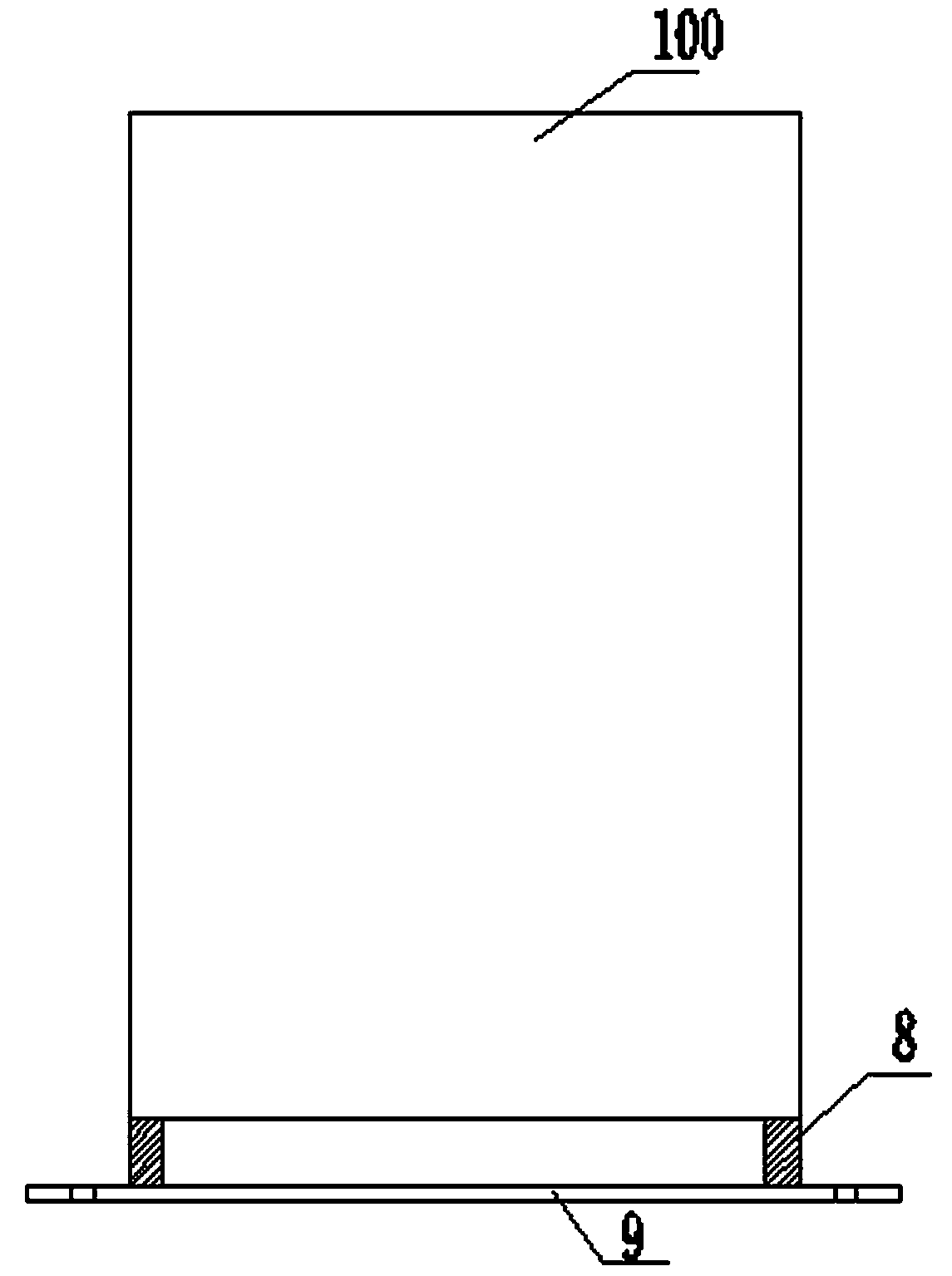
Figure 2 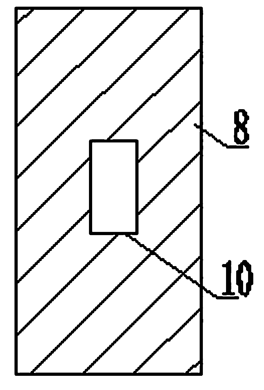
Figure 3
Abstract
Description
technical field
[0001] The invention relates to a split-type air-conditioning system, in particular to a method and device for measuring the weight of refrigerant in an air-conditioning system, and an air-conditioning system using the device. Background technique
[0002] The weight of the refrigerant in the air-conditioning system closely affects the use of the air-conditioner. Many after-sales problems in the air-conditioning industry are caused by abnormal refrigerants.
[0003] In the prior art, due to the complex installation structure of the air conditioning system, the calculation of the weight of the refrigerant in the industry is still at the stage of evaluation, that is, the engineer calculates the weight of the refrigerant based on his personal engineering experience and with reference to parameters such as system pressure, operating frequency, and degree of subcooling. Estimate whether the refrigerant is too much or too little. The estimation result obtained by t...
Examples
Embodiment Construction
[0022] Figure 1 to Figure 3 What is shown is a specific embodiment of the present invention, which mainly calculates the weight of the refrigerant by weighing the weight difference of the outdoor unit 100 of the air conditioning system.
[0023] Such as figure 1 As shown, the outdoor unit 100 of the air conditioning system of the present invention is provided with a first electromagnetic valve 1, a compressor 2, a heat exchanger 3, and a second electromagnetic valve 4 connected in sequence, and the first electromagnetic valve 1 is arranged on the pipe of the outdoor unit. At the entrance of the pipeline 5, the second electromagnetic valve 4 is arranged at the outlet of the pipeline 5 of the outdoor unit.
[0024] Such as figure 2 As shown, in this embodiment, the outdoor unit 100 is connected to the fixed base 9 through the support column 8, and the fixed base is fixed to the ground by bolts.
[0025] Such as image 3 As shown, there is a stress plate 10 attached to the ...