
A New Type of Cable Shrinking Device
A shrinking device and cable technology, which is applied in the installation of cables, the arrangement of cables between relatively moving parts, and electrical components, etc., can solve the problems of easy winding and knotting of cables, difficult control of cable length, and inconvenient use, etc., to achieve The effect of reducing winding or knotting, reasonable design, and increasing comfort
Patent Information
- Authority / Receiving Office
- CN · China
- Patent Type
- Patents(China)
- Current Assignee / Owner
- Publication Date
- 2020-05-05
Smart Images
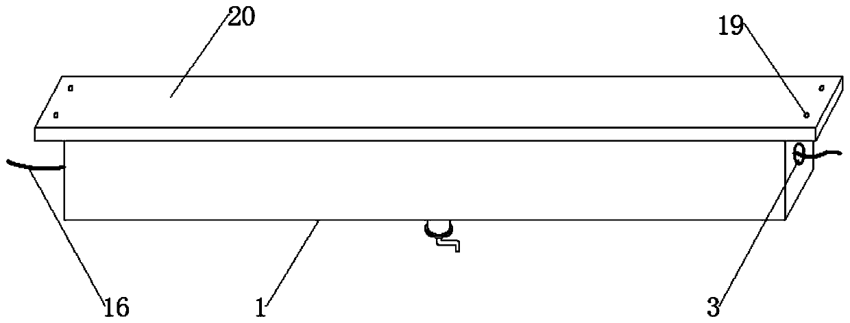
Figure 1 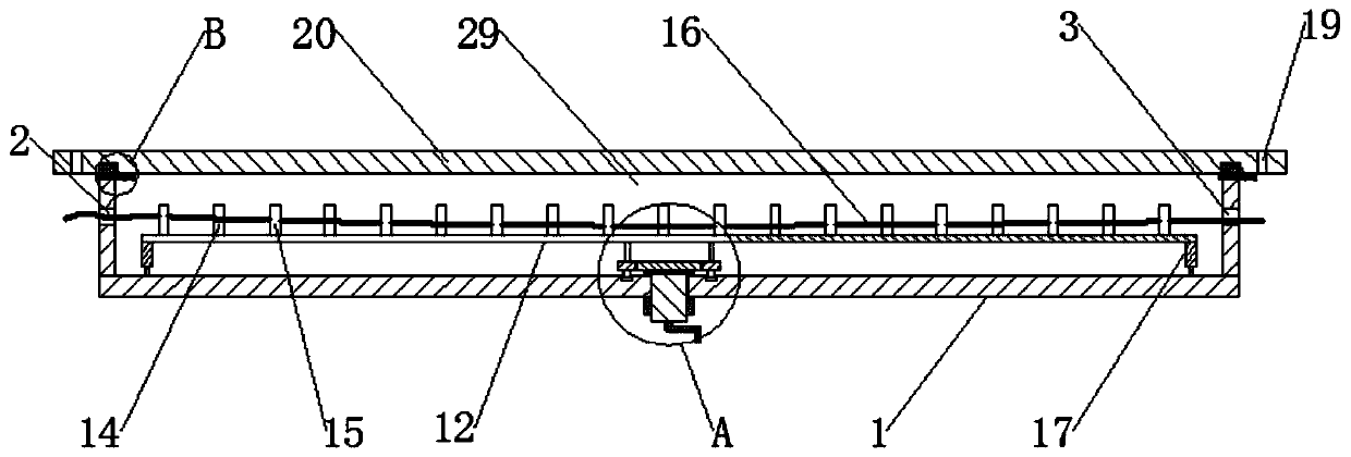
Figure 2 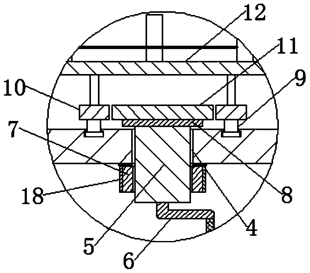
Figure 3
Abstract
Description
technical field
[0001] The present invention relates to the field of cables, and more specifically relates to a novel cable shrinking device. Background technique
[0002] The cable is usually a rope-like cable twisted by several or several groups of conductors (at least two in each group). Each group of conductors is insulated from each other and is often twisted around a center. Insulating covering. Most of them are erected in the air or installed underground or underwater for telecommunications or power transmission. An insulated wire consisting of one or more mutually insulated conductive cores placed in a sealed sheath. A protective covering can be added to the outside for transmission, distribution of electrical energy or transmission of electrical signals. The difference between it and ordinary wires is mainly that the cable size is larger and the structure is more complicated. Cables can be divided into power cables, communication cables and control cables accord...
Examples
Embodiment Construction
[0033] The preferred embodiments of the present invention will be described in detail below in conjunction with the accompanying drawings, so that the advantages and features of the present invention can be more easily understood by those skilled in the art, so as to define the protection scope of the present invention more clearly.
[0034] refer to Figure 1-8As shown, a new type of cable shrinking device includes a cable storage box 1, and the cable storage box 1 includes a bottom plate and four side panels, front, rear, left, and right. The inner end of the cable storage box 1 forms a cavity 29 and the cable storage box 1 The upper end of the cable is open, the cable 16 is placed in the cable storage box 1, the left and right side panels of the cable storage box 1 are respectively provided with a wire supply hole 2 and a wire outlet hole 3, and the bottom plate of the cable storage box 1 is provided with a rotating channel The hole 4, the rotation through hole 4 is inserte...