
A Double Cylindrical Cam Clamp with Locking Mechanism
A locking mechanism, cylindrical cam technology, applied in the direction of clamping, manufacturing tools, metal processing mechanical parts, etc., can solve the problems of the clamping plate not being able to perform linear motion, tightening angle, uneven clamping force, and no self-locking function, etc. Achieve the effect of compact structure, low cost and strong practicability
Patent Information
- Authority / Receiving Office
- CN · China
- Patent Type
- Patents(China)
- Current Assignee / Owner
- Publication Date
- 2021-06-18
- Estimated Expiration
- Not applicable · inactive patent
Smart Images
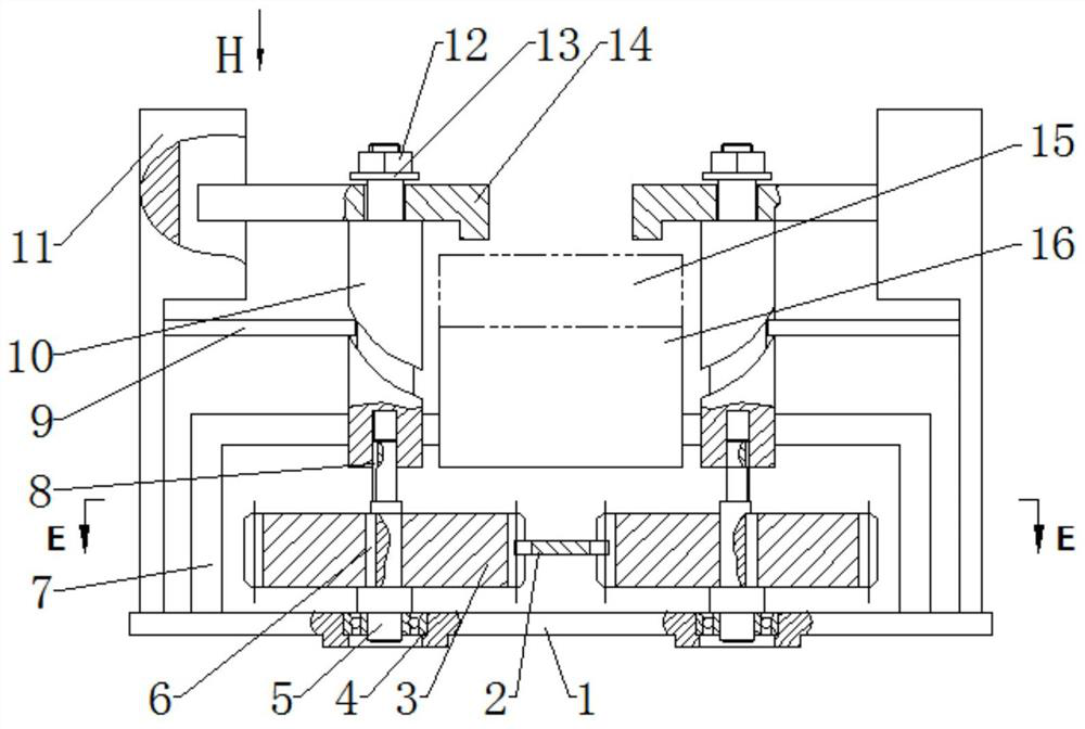
Figure 1 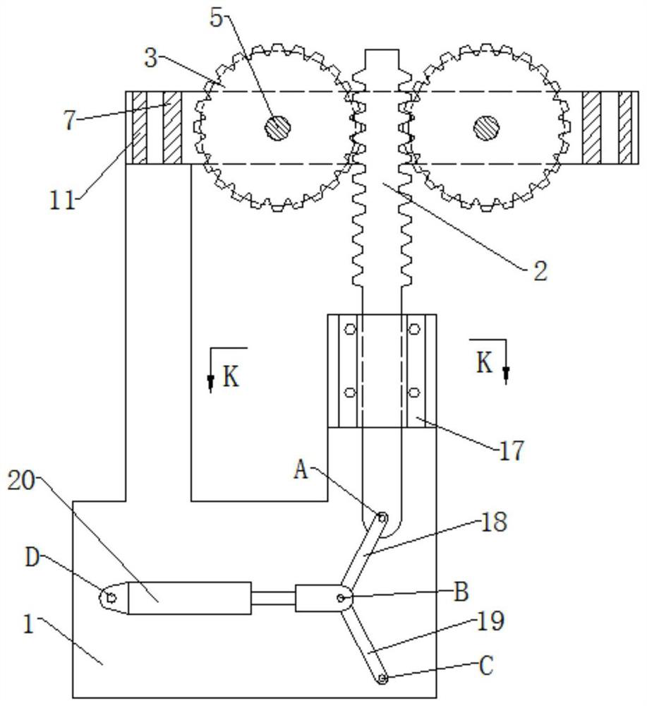
Figure 2 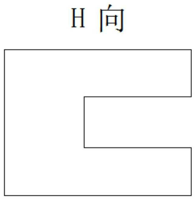
Figure 3
Abstract
Description
technical field
[0001] The invention belongs to the technical field of clamps for mechanical processing, and in particular relates to a double cylindrical cam clamp with a locking mechanism. Background technique
[0002] At present, the clamping mechanism on the market either has no self-locking function, or when the workpiece has a machining error, the clamped surface of the workpiece cannot fully contact the pressing block, or the clamping plate cannot do linear motion, and the clamping angle is different for different workpieces. Uneven clamping force. In view of the above reasons, the market is in urgent need of a fixture with self-locking, constant clamping angle when the workpiece size changes, and a clamping surface that can fully contact the workpiece. Contents of the invention
[0003] In view of this, the present invention provides a double cylinder cam clamp with a locking mechanism to solve the deficiencies in the prior art.
[0004] Technical scheme of the p...
Examples
Embodiment 1
[0023] A double-cylindrical cam clamp with a locking mechanism, comprising a frame 1, on which a rack 2 arranged horizontally and a transmission device for driving the rack 2 to move back and forth, the output of the transmission device The other end of the rack 2 is connected to one end of the rack 2, and the other end of the rack 2 meshes with two symmetrically arranged gears 3 respectively, and the gear 3 is sleeved on the lower end of the gear shaft 5 and fixed with the gear shaft 5 by a positioning key 6, One end of the gear shaft 5 is vertically erected on the frame 1 through the bearing 4, and the other end of the gear shaft 5 is clearance-fitted with the cylindrical cam 10 through the guide key 8 so that the cylindrical cam 10 can rotate synchronously with the gear shaft 5 and the cylindrical cam 10 and the gear shaft 5 have relative movement, and the end of the cylindrical cam 10 away from the gear shaft 5 is sequentially fitted with a pressure plate 14 and a limiting ...