
Vertical vibration isolation device
A vibration damping device, vertical technology, applied to building components, high internal friction springs, shockproof, etc., can solve the problems of small vertical stiffness, harsh working environment, easy resonance and high-frequency vibration transmission, etc., to avoid torsion Deformation, broad application prospects, and the effect of improving installation efficiency
Patent Information
- Authority / Receiving Office
- CN · China
- Patent Type
- Applications(China)
- Current Assignee / Owner
- Publication Date
- 2020-06-26
- Estimated Expiration
- Not applicable · inactive patent
Smart Images
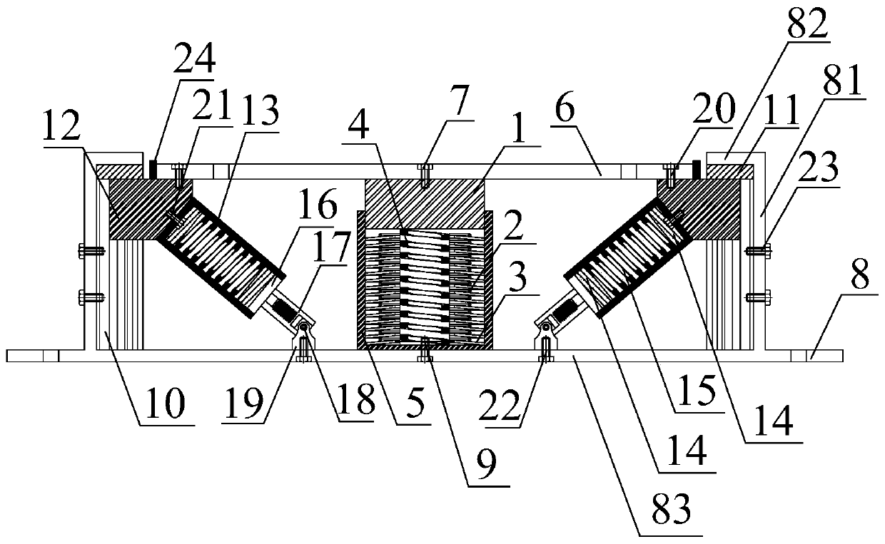
Figure 1 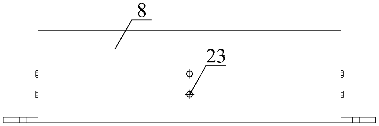
Figure 2 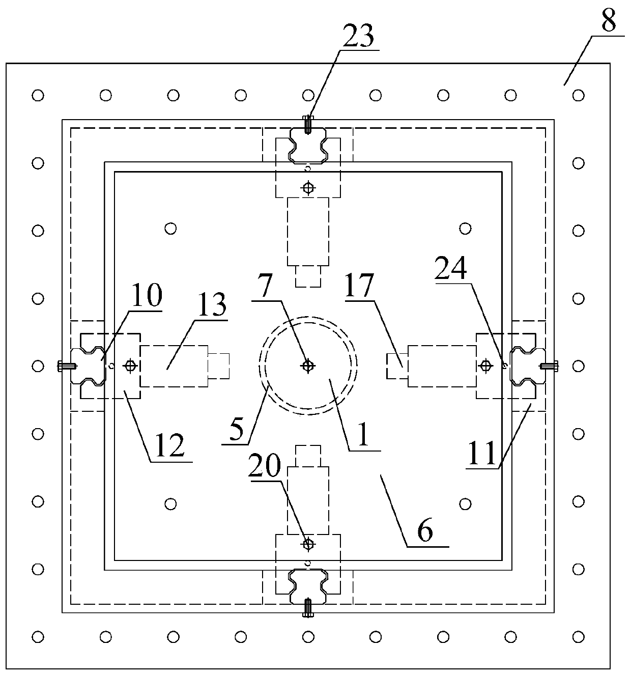
Figure 3
Abstract
Description
technical field
[0001] The invention relates to a vertical vibration isolation device, which belongs to the technical field of vibration isolation in civil engineering and mechanical engineering. Background technique
[0002] With the increase of my country's urbanization rate, urbanization is gradually developing towards urbanization, and urban land is in short supply. The development of rail transit has become the most effective way to solve urban traffic. Rail transit lines will pass through populated areas and some urban buildings, which is bound to It brings vibration to the personnel and equipment in the building. In particular, for rail transit, the foundation of the superstructure is directly arranged on the vibration source excitation caused by the subway, resulting in a greater impact on the environment than the buildings along the track. , which brings the problem of vibration comfort caused by urban rail transit, it is necessary to take corresponding vibration cont...
Examples
Embodiment 1
[0052] Embodiment 1: see figure 1 and figure 2
[0053] see image 3 , as an example, this embodiment is provided with 4 sets of damping devices. Under the action of vertical vibration, the 4 sets of damping devices are linked together to reduce the vertical vibration. The 4 sets of devices are placed symmetrically to prevent the structure or equipment Unsteady.
[0054] Figure 4 It is a schematic diagram of the construction of an adaptive stiffness element, and a schematic diagram of the construction of a disc spring group, see Figure 5 , see the three-dimensional view of the preloaded rectangular spring Figure 6 . The positioning loading ring 2 and the disc spring 3 work in parallel to provide vertical negative stiffness, the pre-compressed rectangular spring 4 is in contact with the actuating block 1, and the disc spring group and the actuating block 1 reserve a gap of 5-8mm to ensure the pre-compressed rectangular The larger positive stiffness provided by the sp...