
Azimuth element and distortion calibration method in interferometric imaging spectrometer
A technology of imaging spectrometer and internal azimuth elements, which is applied in the field of optical precision measurement, and can solve the problems of low calibration accuracy
Patent Information
- Authority / Receiving Office
- CN · China
- Patent Type
- Patents(China)
- Current Assignee / Owner
- Publication Date
- 2021-09-14
Smart Images
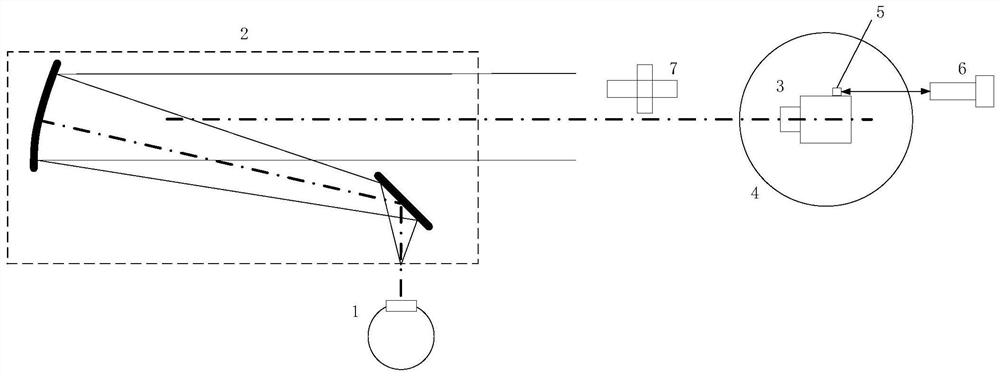
Figure 1 
Figure 2 
Figure 3
Abstract
Description
technical field
[0001] The invention belongs to the technical field of optical precision measurement, and relates to a calibration device for azimuth elements and distortions in an interferometric imaging spectrometer, which is suitable for high-precision measurement of the internal parameters of a camera with a small field of view, and is especially suitable for azimuth elements and distortions in an interferometric imaging spectrometer Measurement. Background technique
[0002] With the development of aerospace technology, the geometric accuracy of the image information acquired by space cameras is becoming higher and higher. The calibration of internal orientation elements and distortion has become an important task and has been extensively studied in recent years. Some universities and research institutes at home and abroad have carried out more research on the calibration of internal orientation elements and distortion, focusing on the target position extraction algorit...
Examples
Embodiment Construction
[0042] The present invention will be further described below in conjunction with accompanying drawing.
[0043] Such as figure 1 As shown, the azimuth element and distortion calibration device in the interferometric imaging spectrometer provided by the present invention includes an integrating sphere light source 1, a collimator 2, a two-dimensional turntable 4, a high-precision cube mirror 5, a high-precision angle measuring device 6 and an automatic Collimated theodolite7.
[0044] The integrating sphere light source 1 is located behind the focal plane of the collimator 2 and is used to uniformly illuminate the reticle target at the focal plane of the collimator 2 .
[0045] Collimator 2 is used to simulate an infinite target;
[0046] The two-dimensional turntable 4 is located directly in front of the light outlet of the collimator 2, and the table height of the two-dimensional turntable 4 is lower than the height of the bottom of the light outlet of the collimator 2; Be...