
Pipe orifice correction device capable of achieving rapid alignment and alignment method of pipe orifice correction device
A technology of a correction device and a positive tube, which is applied in the field of quickly aligning the nozzle correction device, can solve the problems of discount of correction effect, not limited to a certain point or a certain orientation, and limit of the lifting direction, etc.
Patent Information
- Authority / Receiving Office
- CN · China
- Patent Type
- Applications(China)
- Current Assignee / Owner
- Publication Date
- 2020-12-15
Smart Images
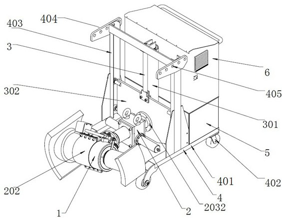
Figure 1 
Figure 2 
Figure 3
Abstract
Description
technical field
[0001] The invention relates to a correction device, in particular to a fast alignment correction device and a correction method thereof. Background technique
[0002] For large-diameter steel pipes, it is inevitable that the mouth of the pipe will be congenitally out of round during manufacturing and processing. During the storage, transfer and use of the steel pipe, the mouth of the pipe will also be deformed and out of round due to extrusion and collision. The out-of-roundness of the nozzle seriously affects the installation and docking, and it must be corrected and returned to the circle first. There are many methods for nozzle calibration. The current mainstream method is to use a hydraulic jack to radially prop up the tube wall inside the nozzle for calibration. The calibration accuracy is guaranteed by controlling the stroke of the jack. This method is effective. Compared with general mechanical The formula calibration method saves much time and effor...
Examples
Embodiment Construction
[0028] The present invention will be further explained below in conjunction with the accompanying drawings and embodiments.
[0029] In order to make the technical means, creative features, goals and effects achieved by the present invention easy to understand, the present invention will be further described below in conjunction with specific embodiments.
[0030] like figure 1As shown, a nozzle correction device for fast alignment, the nozzle correction machine is composed of a correction hydraulic mechanism 1, a rotating clamping mechanism 2, a lifting mechanism 3, a walking mechanism 4, a hydraulic pump station 5 and a control cabinet 6. The correction hydraulic mechanism 1 is clamped by the clamper 202 at one end of the rotary clamping mechanism 2, and connected with the lifting installation plate 302 of the lifting mechanism 3 through the connecting flange 2032 at the other end. The lifting mechanism 3 is installed inside the traveling mechanism 4, The lifting installati...