
A gas pipeline with integrated cooling channel
A technology for cooling channels and gas pipelines, which is applied to jet propulsion devices, machines/engines, rocket engine devices, etc. It can solve problems such as difficulty in quality consistency control, low integration, and long processing cycle, so as to avoid local temperature The effects of excessively high, simplified process, and reduced development cost
Patent Information
- Authority / Receiving Office
- CN · China
- Patent Type
- Patents(China)
- Current Assignee / Owner
- Publication Date
- 2021-10-19
Smart Images
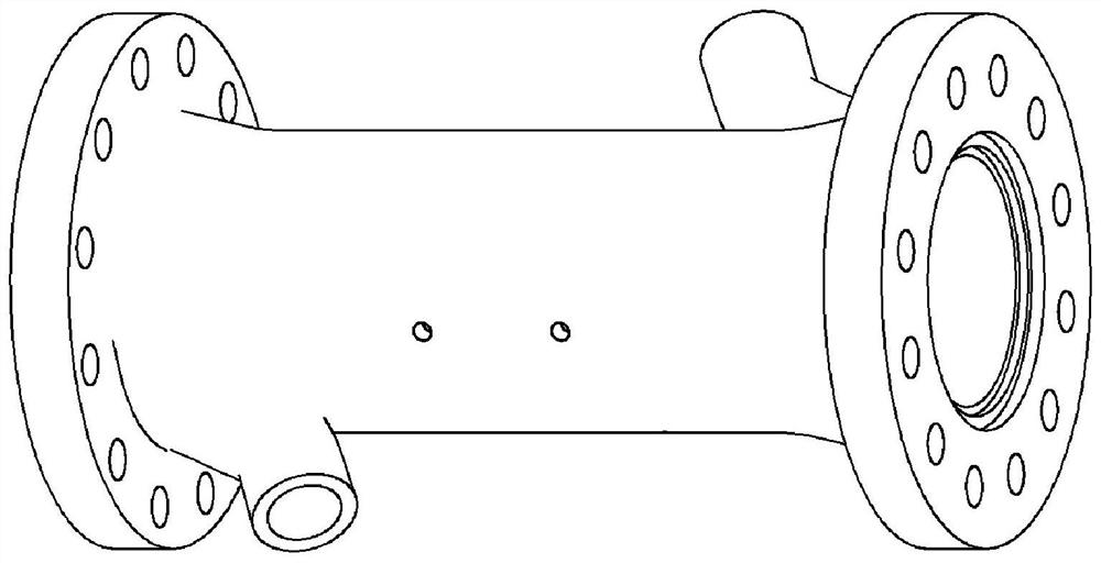
Figure 1 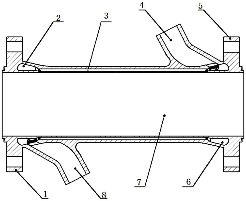
Figure 2 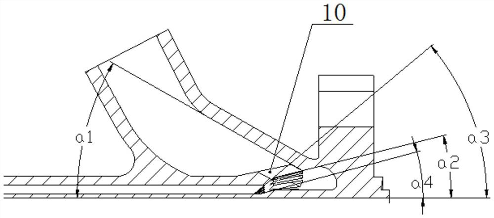
Figure 3
Abstract
Description
technical field
[0001] The invention relates to a gas pipeline with an integrated cooling channel, which can be used as a connection structure between a gas generator of a liquid rocket engine and a rear-end assembly. Background technique
[0002] As a thermomechanical power device, a large number of gas pipelines that withstand high temperature and high pressure are distributed in the liquid rocket engine and its supporting test system. Considering working in a high temperature and high pressure environment for a long time, in order to improve work reliability and To control thermal deformation, the gas pipeline is generally equipped with a cooling structure. When the traditional cooling structure is processed, the cooling tank is often separated from the outer wall, and connected by brazing and other processes, and then the liquid collection chamber, inlet and outlet pipes, flanges and other parts are connected by welding. The overall process is complicated and the circula...
Examples
Embodiment Construction
[0041] The present invention will be described in detail below in conjunction with the accompanying drawings.
[0042] Such as Figure 1-2 As shown, the gas pipeline of the integrated cooling channel provided by the present invention includes a gas channel 7, a first flange 1 and a second flange 5 respectively arranged at both ends of the gas channel 7, and a gas channel arranged on the side wall of the gas channel 7 The cooling medium inlet pipe joint 4 and the cooling medium outlet pipe joint 8, wherein the cooling medium inlet pipe joint 4 is closer to the second flange 5, and the cooling medium outlet pipe joint 8 is closer to the first flange 1.
[0043] Both the cooling medium inlet pipe joint 4 and the cooling medium outlet pipe joint 8 adopt a gradually expanding form, and the overall shape is like a spout; the cooling water inlet end section of the cooling working medium inlet pipe joint 4 is circular, and the cooling water outlet end section is circular. It is ellipti...