
Production line for manufacturing crushed peanuts
A peanut crushing and production line technology, which is used in centrifuges with rotating drums, centrifuges, solid separation and other directions, can solve the problems of excessive residual oil and poor particle uniformity in crushed peanuts.
Patent Information
- Authority / Receiving Office
- CN · China
- Current Assignee / Owner
- Publication Date
- 2021-04-30
Smart Images
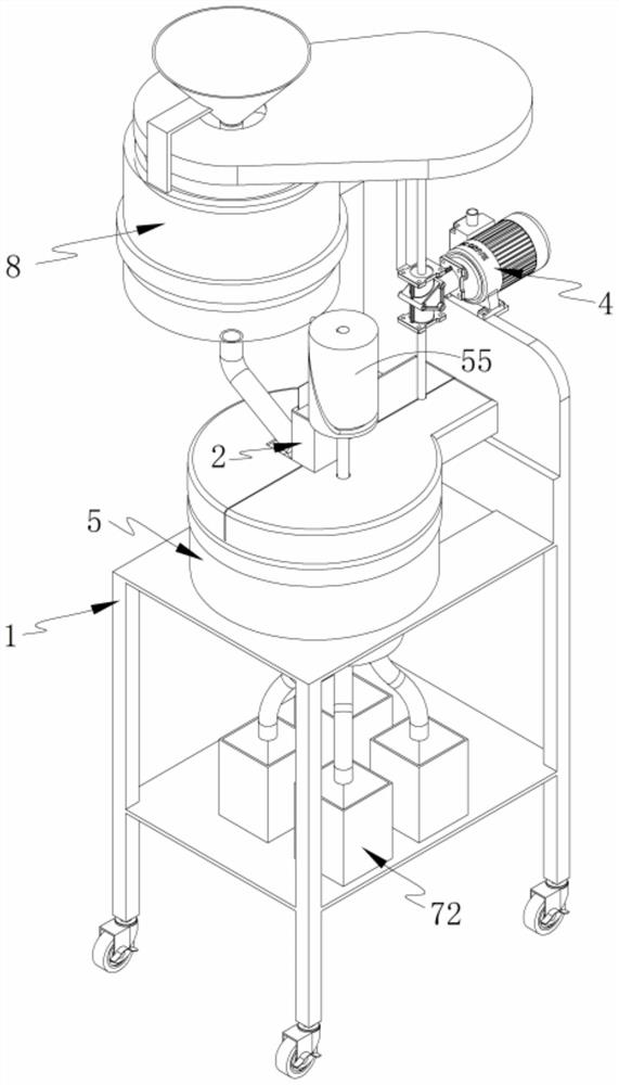
Figure 1 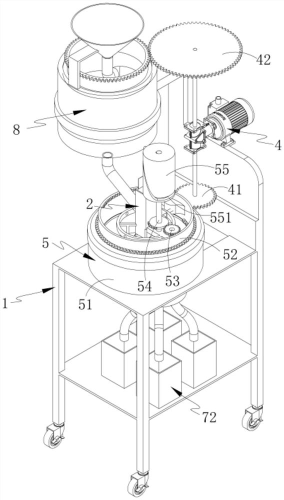
Figure 2 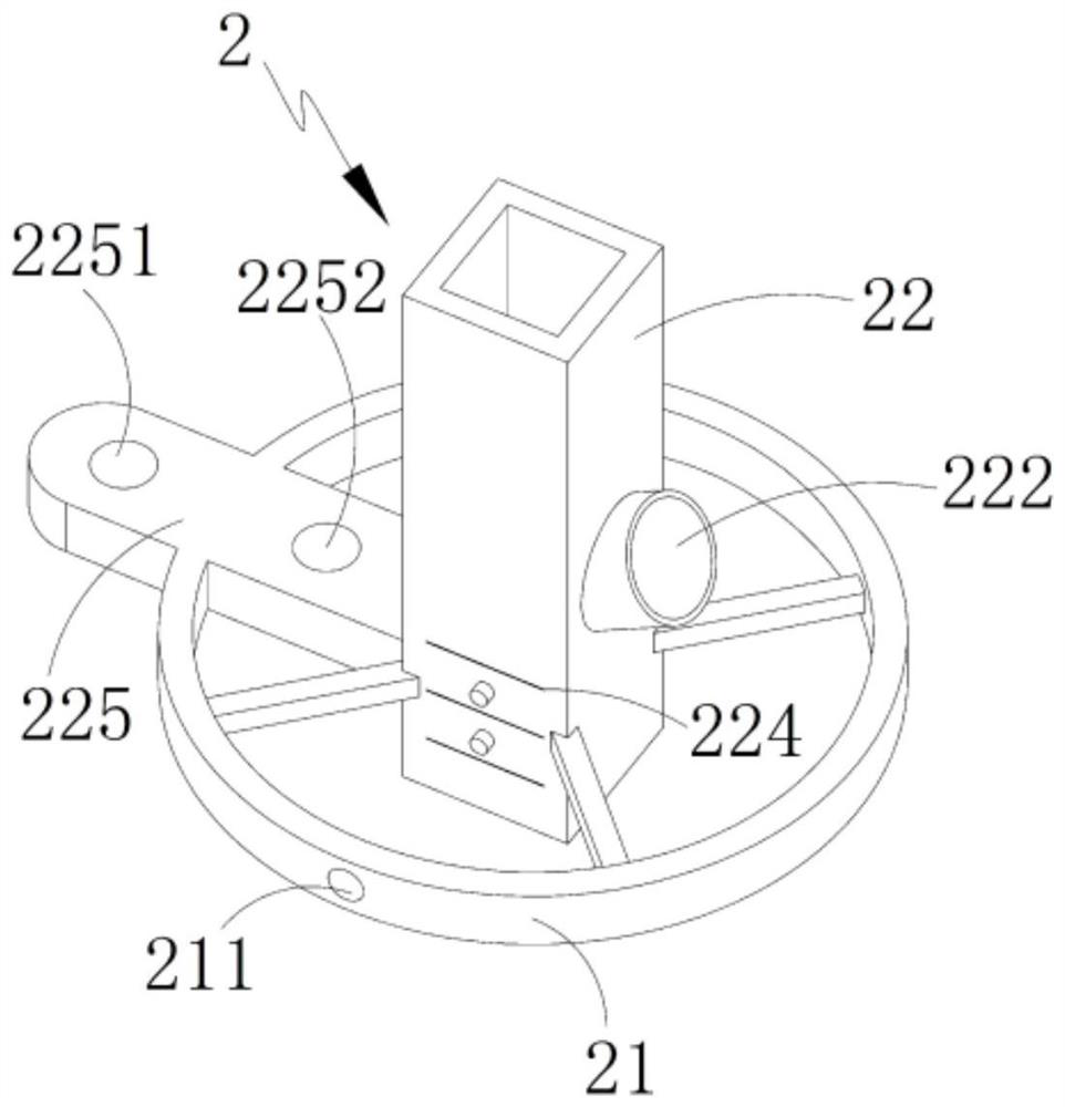
Figure 3
Abstract
Description
technical field
[0001] The invention relates to the technical field of food processing, in particular to a production line for making crushed peanuts. Background technique
[0002] Crushed peanuts are an indispensable ingredient in traditional Chinese cuisine. Peanuts can be added to hot pot, toast, cold dishes, snacks, etc. to make the food taste more delicious. Some crushed peanuts are made by drying peanuts, and some The preparation method is to make crushed peanuts after frying.
[0003] Chinese invention patent 201810091786.0 discloses a crushed peanut processing device for food processing, which belongs to the field of food processing equipment. The crushing device is installed on the top of the second bracket, the top of the screen is connected with the first bracket and the second bracket, two of the baffles are respectively fixed on the left and right sides of the screen, and the collection tank is fixed On the square hole at the front end of the workbench, the wo...
Examples
Embodiment 1
[0062] Such as Figure 1-2 As shown, a production line for making crushed peanuts, including frame 1, also includes:
[0063] Tool holder unit 2, such as Figure 3-4 As shown, the tool rest unit 2 is arranged on the frame 1, which includes an annular connecting frame 21 arranged above the frame 1 and a tool rest 22 arranged in the annular connecting frame 21; The bottom of 22 is provided with crushed peanut outlet 221, and its side is provided with feeding port 222 inclined; One side is provided with a transverse guide groove 224 under the feed port 222, and the other side is provided with a connecting plate 225 connecting the knife rest 22 and the annular connecting frame 21, and the connecting plate 225 is provided with a through hole a2251 and A through hole b2252; a guide hole 211 is provided at a position corresponding to the guide groove 224 on the annular connecting frame 21;
[0064] Cutter unit 3, such as Figure 5-7 As shown, the cutter unit 3 is arranged on the ...
Embodiment 2
[0096] Such as Figure 14 , 16 -18, wherein the same or corresponding parts with the first embodiment adopt the corresponding reference numerals with the first embodiment, for the sake of simplicity, only the difference between the first embodiment and the first embodiment is described below; the second embodiment is different from the first embodiment The difference is that:
[0097] Among them, such as Figure 14 As shown, the fried peanuts enter the oil draining unit 8, and the driving unit 4 drives the conical rotating disc 83 to rotate, so that the peanuts spiral down along the spiral oil draining pipe 84 and centrifugally drain the oil. The oil flows out through the oil draining hole 842 and along the cone The inwall of shaped rotating disk 83 flows into oil receiving groove 85, and the peanut that oil draining is finished enters in the knife rest 22 through the outlet of spiral oil draining pipe 84.
[0098] Among them, such as Figure 16 As shown, at this time, the...