
Cooling device for alloy material production
A technology of cooling device and alloy material, which is applied in the direction of furnace material, charging treatment type, lighting and heating equipment, etc., and can solve the problems of impurity precipitation, pipeline blockage, cooling effect decline, etc.
Patent Information
- Authority / Receiving Office
- CN · China
- Patent Type
- Applications(China)
- Current Assignee / Owner
- Publication Date
- 2021-12-24
Smart Images
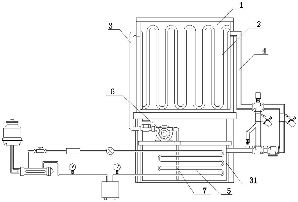
Figure 1 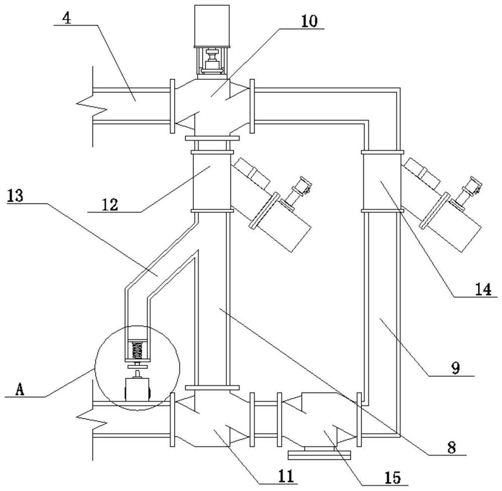
Figure 2 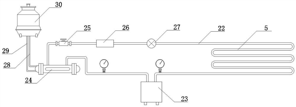
Figure 3
Abstract
Description
technical field
[0001] The invention relates to the technical field of alloy production, in particular to a cooling device for alloy material production. Background technique
[0002] A metal material with metallic properties that is usually formed by adding two or more metal elements or other non-metallic elements based on metals through an alloying process (smelting, mechanical alloying, sintering, vapor deposition, etc.) is called an alloy. .
[0003] Melting is a technique for producing alloys by melting metallic materials such as aluminum and iron together at high temperatures. Alloys are generally made by smelting in a smelting furnace. During the smelting process, it was found that after the smelting of the low-carbon ferrochrome alloy was completed, the temperature of the smelting furnace was too high to cool quickly, and it could only be cooled by natural cooling. Hidden dangers, at the same time, the staff need to wait a lot of time to clean the melting furnace, ...
Examples
Embodiment 1
[0039] A cooling device for the production of alloy materials, comprising a furnace 1, the interior of the furnace 1 is provided with a water cooling wall 2, the water cooling wall 2 is connected with a water inlet pipe 3 and a water outlet pipe 4, one end of the water inlet pipe 3 is connected with a water cooling box 31, and the water outlet pipe One end of 4 is connected to the water-cooled box 31, the outlet pipe 4 is connected with a filter module, and the water-cooled box 31 is provided with an evaporating pipe 5 inside, and the evaporating pipe 5 is connected with a cooling module; The water inlet of the pump 6 is connected with a water suction pipe 7 , and the water suction pipe 7 is located inside the water cooling box 31 .
[0040] (see figure 1 )
[0041]The filter module includes a working filter tube 8 and a spare filter tube 9. One end of the working filter tube 8 is connected to the outlet pipe 4, the other end of the working filter tube 8 is connected to an el...
specific Embodiment approach
[0046] 1. A smelting barrel is set in the furnace 1, and the smelting barrel is located between the water walls 2;
[0047] Two, the melting furnace 1 starts the circulating pump 6 after the smelting is finished, and the circulating pump 6 extracts the coolant in the water-cooled tank 31 through the suction pipe 7, and imports it into the water-cooled wall 2 through the water inlet pipe 3 to cool the smelting barrel;
[0048] 3. After passing through the water wall 2, the coolant passes through the outlet pipe 4 and is introduced into the working filter pipe 8 by the electric three-way valve 10. The working filter 12 filters the coolant, and at the same time, part of the coolant enters the guide pipe 13, and the fluid of the coolant The pressure makes the piston plate 19 drive the compression spring 21 to press down, and the piston plate 19 drives the push plate 20 to descend through the slide rod 18 to trigger the travel switch 17, and the travel switch 17 controls the electri...