
Method and apparatus for measuring photoacoustic signal in biological tissue by ultrasonic beams
A biological tissue and acoustic signal technology, applied in the field of measurement, can solve problems such as poor signal-to-noise ratio, undetectable signal, weak photoacoustic signal, etc., and achieve the effects of easy assembly, improved signal-to-noise ratio, and convenient operation
Patent Information
- Authority / Receiving Office
- CN · China
- Patent Type
- Patents(China)
- Current Assignee / Owner
- Publication Date
- 2004-09-29
- Estimated Expiration
- Not applicable · inactive patent
Smart Images
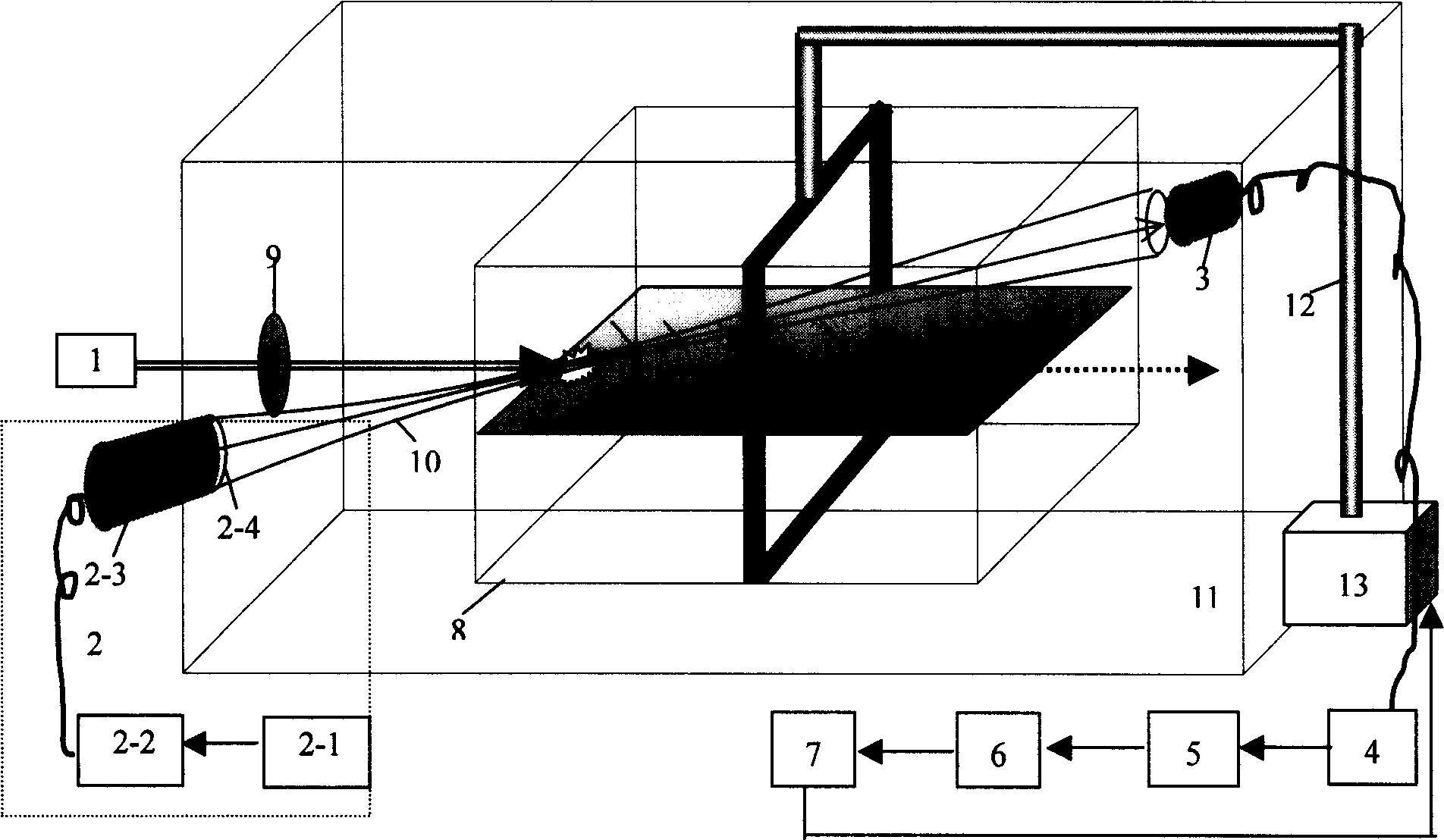
Figure 1 
Figure 2 
Figure 3
Abstract
Description
technical field
[0001] The invention relates to measurement technology, in particular to a method for measuring photoacoustic signals of biological tissues with a probe ultrasonic beam.
[0002] The invention also relates to a device for use in a method of measuring photoacoustic signals of biological tissue with a probe ultrasound beam. Background technique
[0003] In recent years, the research and application of the photoacoustic effect has received more and more attention. When a certain object is irradiated with light, its internal temperature will change due to its absorption of light, which will cause changes in the mechanical parameters of its local area; when a pulsed light source or modulated light source is used, the fluctuation of the local temperature inside the object will cause Its volume expands and contracts, so it can radiate sound waves outward. This phenomenon is called photoacoustic field effect (referred to as photoacoustic e...
Examples
Embodiment Construction
[0028] Such as figure 1 As shown, the device of the present invention is mainly composed of a laser 1, an ultrasonic generating assembly 2, an acoustic signal measuring assembly 3, a signal amplifier 4, a data acquisition card 5, a real-time Fourier transform module 6, and a computer 7; wherein the ultrasonic generating assembly 2 is composed of a function generator 2-1, the power amplifier 2-2, the ultrasonic transducer 2-3 and the ultrasonic lens 2-4 are sequentially connected to form; wherein the ultrasonic lens 2-4 is fixed with the ultrasonic transducer 2-3 by a screw cover, and other connections are sequentially It is an electrical connection; the ultrasonic generating component 2 is acoustically connected to the acoustic signal measuring component 3; the acoustic signal measuring component 3, the signal amplifier 4, the data acquisition card 5, the real-time Fourier transform module 6, and the computer 7 are electrically connected in turn. Other components are: sample 8...