

Transmission gear control apparatus for vehicle
a transmission gear and automatic transmission technology, applied in the direction of gearing control, gearing elements, belts/chains/gearrings, etc., can solve the problems of providing a driver receiving a driver with a sense of discomfort, so as to prevent excess slippage of friction engagement elements and prevent excess slippag
Patent Information
- Authority / Receiving Office
- US · United States
- Patent Type
- Patents(United States)
- Current Assignee / Owner
- Publication Date
- 2019-05-07
- Estimated Expiration
- Not applicable · inactive patent
Smart Images
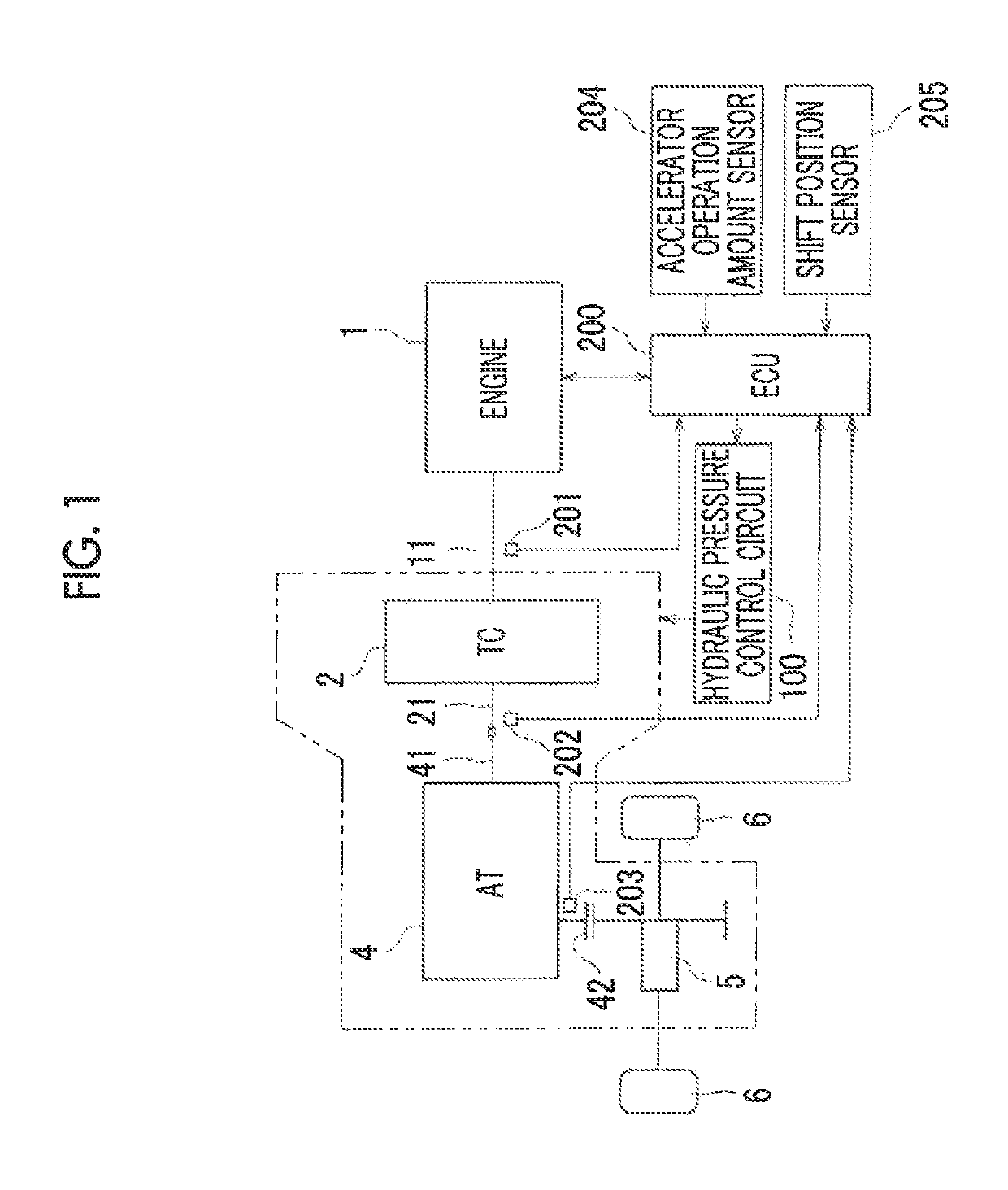
Figure 1 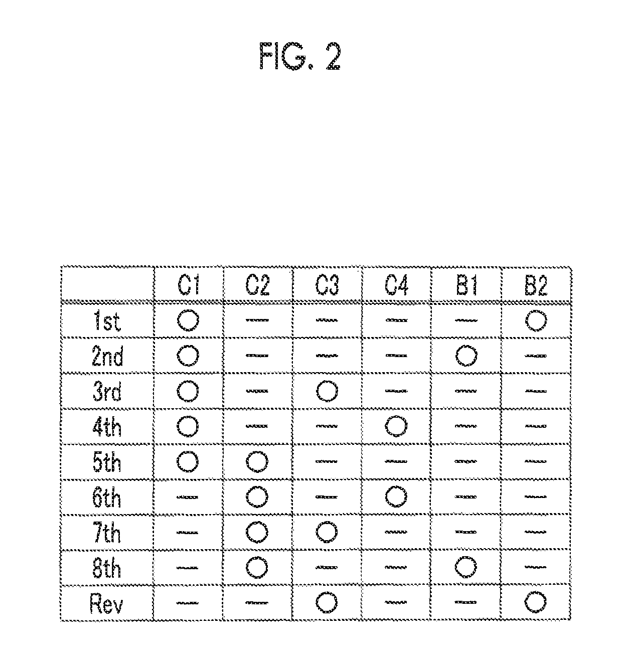
Figure 2 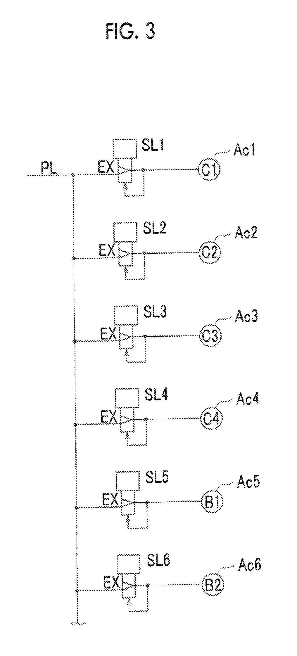
Figure 3
Abstract
Description
INCORPORATION BY REFERENCE
[0001] The disclosure of Japanese Patent Application No. 2016-057042 filed on Mar. 22, 2016 including the specification, drawings and abstract is incorporated herein by reference in its entirety.BACKGROUND1. Technical Field
[0002] The embodiment relates to a transmission gear control apparatus for an automatic transmission mounted on a vehicle and, in particular, to a transmission gear control apparatus that limits input torque when a hydraulic pressure cannot normally be supplied to a friction engagement element such as a clutch or a brake.2. Description of Related Art
[0003] As an automatic transmission that is mounted on a vehicle such as an automobile, a stepped transmission gear mechanism, to which drive power of an engine is transmitted via a torque converter, has conventionally been used. In this transmission gear mechanism, plural transmission gear stages are established by selectively engaging or disengaging plural friction engagement elements such as a...
Examples
Embodiment Construction
[0026]A description will hereinafter be made on one embodiment on the basis of the drawings. In this embodiment, a description will be made on a case where the embodiment is applied to an FF (front-engine, front-wheel-drive) vehicle on which an automatic transmission is mounted. First, a description will be made on an overall configuration of a powertrain of the vehicle.
[0027]FIG. 1 is a schematic configuration diagram of the powertrain of the vehicle according to this embodiment. This vehicle includes an engine 1, a torque converter (TC) 2, an automatic transmission (AT) 4, a differential device 5, drive wheels (front wheels) 6, driven wheels (rear wheels: not shown), a hydraulic pressure control circuit 100, an electronic control unit (ECU) 200, and the like. As one example, the engine 1 is a multi-cylinder gasoline engine, and a crankshaft 11 as an output shaft thereof is coupled to the torque converter 2. A rotational speed of the crankshaft 11 (an engine speed Ne) is detected b...