
Lightweight structure especially for an aircraft and method for making such a structure
a technology for aircraft and lightweight structures, applied in the field of aircraft construction, can solve the problems of low static strength characteristic of fiber reinforced laminates compared to monolithic materials, limited production of fiber reinforced laminates, and high cost of fiber reinforced laminate production, so as to increase the useful life of lightweight structures, reduce crack propagation, and reduce the effect of damage toleran
Patent Information
- Authority / Receiving Office
- US · United States
- Patent Type
- Applications(United States)
- Current Assignee / Owner
- Publication Date
- 2005-05-26
Smart Images
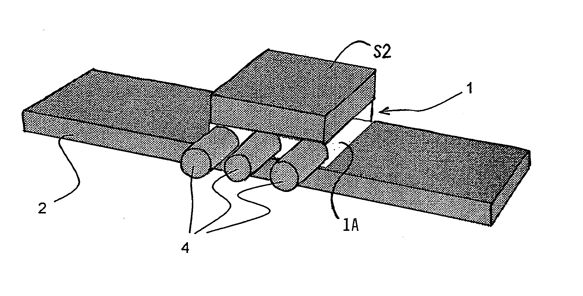
Figure 1 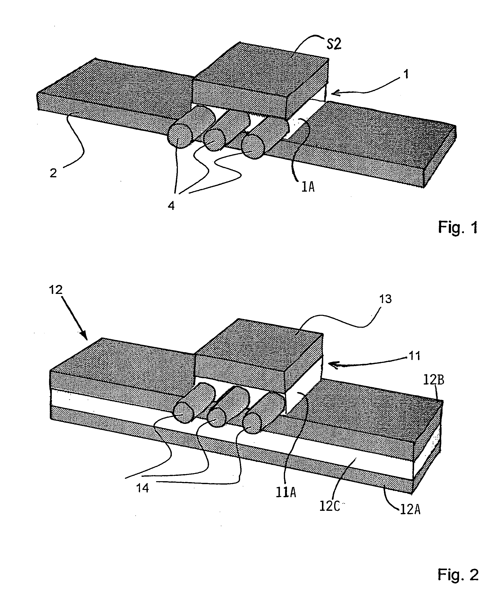
Figure 2 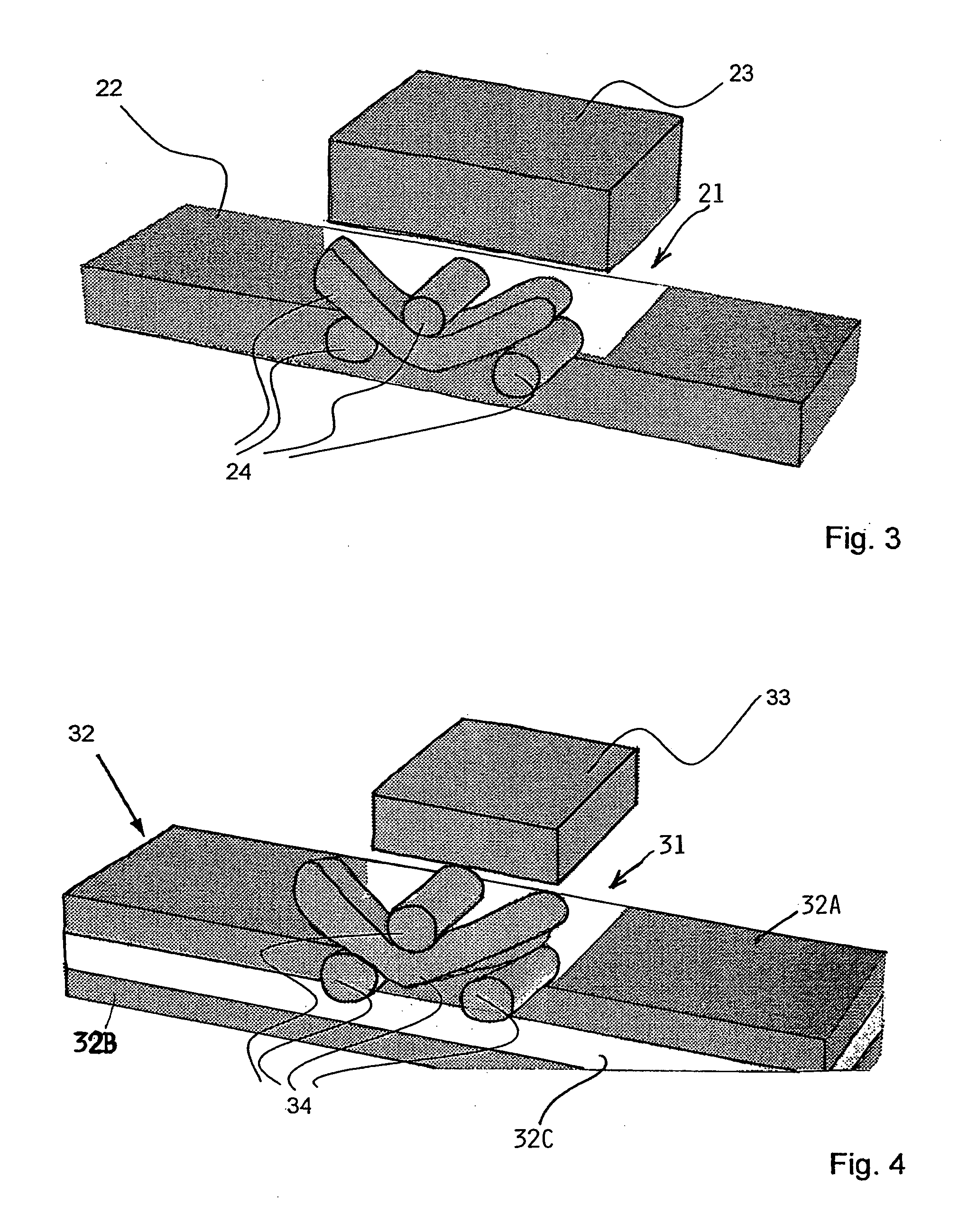
Figure 3
Abstract
Description
PRIORITY CLAIM
[0001] This application is based on and claims the priority under 35 U.S.C. §119 of German Patent Application 103 30 708.7, filed on Jul. 8, 2003, the entire disclosure of which is incorporated herein by reference. FIELD OF THE INVENTION
[0002] Lightweight structures are used primarily in aircraft construction, particularly aircraft bodies including an outer skin adhesively bonded to a framework. The invention also relates to a method for constructing such a lightweight structure by adhesive bonding. BACKGROUND INFORMATION
[0003] Lightweight structures for use in the aircraft and spacecraft technologies include an outer skin which is strengthened on its inner surface by a reinforcement or stiffening framework. Such a framework is in fact a three dimensional structure but may be referred to as being “two-dimensional” to distinguish the framework from a three-dimensional aircraft or spacecraft body. An aircraft body, for example, is constructed as a lightweight structur...
Examples
Embodiment Construction
[0023]FIG. 6 shows a view onto a broken away section of an aircraft lightweight body structure including a frame or framework FW of ribs R1, R2, R3 extending circumferentially around the longitudinally aircraft axis while stringers S1, S2, S3 extend parallel to the longitudinal aircraft axis. The ribs and stringers are adhesively bonded to the inwardly facing surface of an outer skin 2. A plane extending perpendicularly to the plane of the sheet of the drawing and designated by arrows I-I illustrates the position of a reinforcing layer in the perspective view of FIG. 1 between the outer skin 2 and a stringer S2 in the framework FW. More specifically, the reinforcement layers according to the invention are positioned between the outer skin 2 and the ribs, or between the outer skin and the stringers or between the outer skin and the ribs and stringers.
[0024]FIG. 1 shows a reinforcing layer 1 bonded by an adhesive matrix 1A to an outer skin 2 and to a stringer S2. The reinforcing laye...