
Optical waveguide module
a technology of optical waveguides and modules, applied in the direction of optical waveguide light guides, instruments, optics, etc., can solve the problems of increasing the number of optical components, increasing the complexity of varying the photosensitivity of the reflected light at the photodetector, so as to simplify the structure and manufacturing process of the optical circuit.
Patent Information
- Authority / Receiving Office
- US · United States
- Patent Type
- Applications(United States)
- Current Assignee / Owner
- Publication Date
- 2005-06-02
- Estimated Expiration
- Not applicable · inactive patent
Smart Images
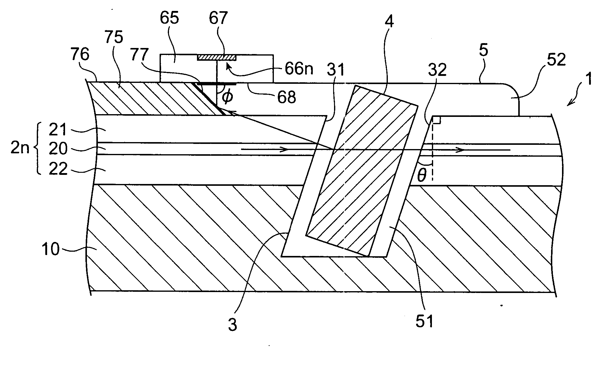
Figure 1 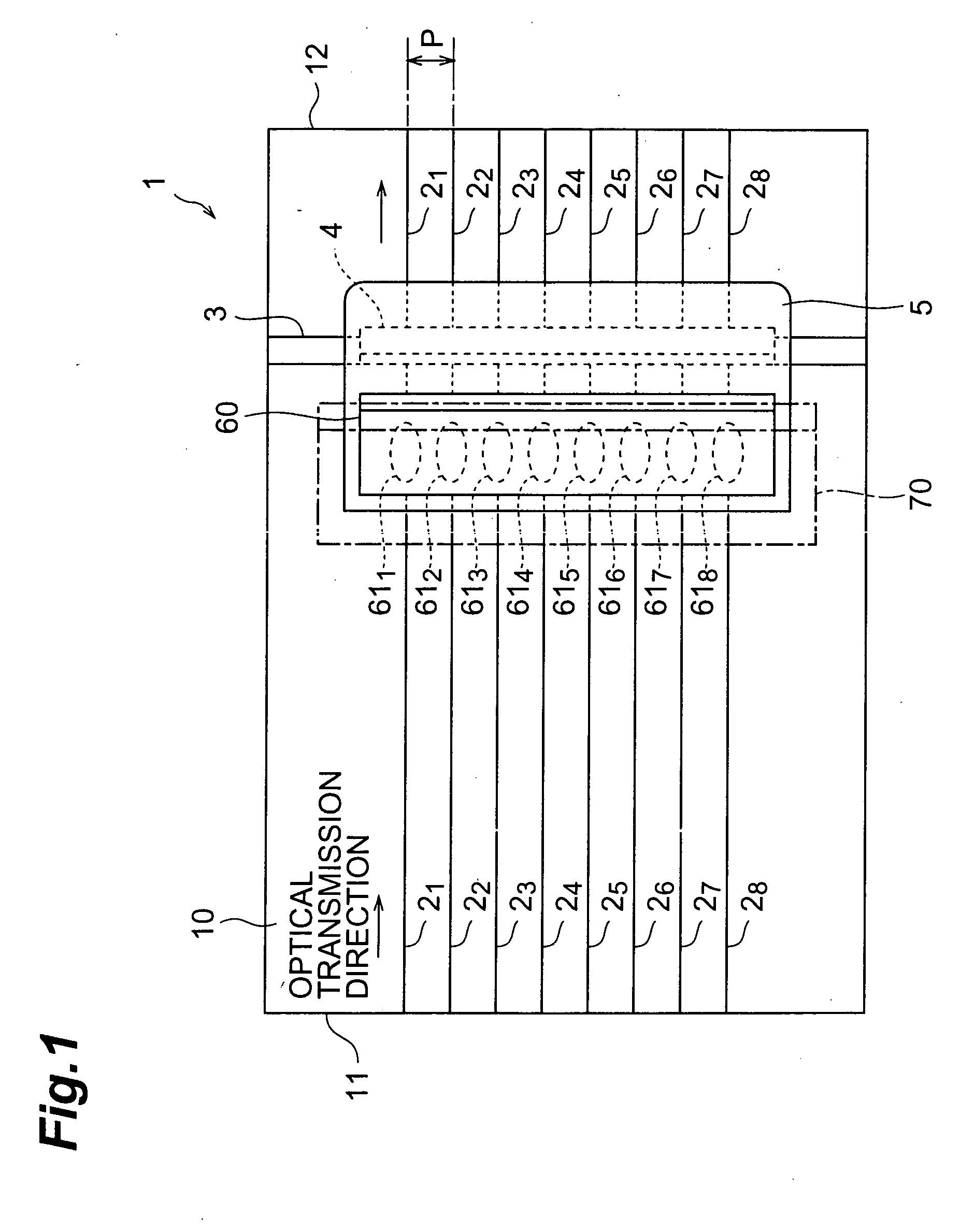
Figure 2 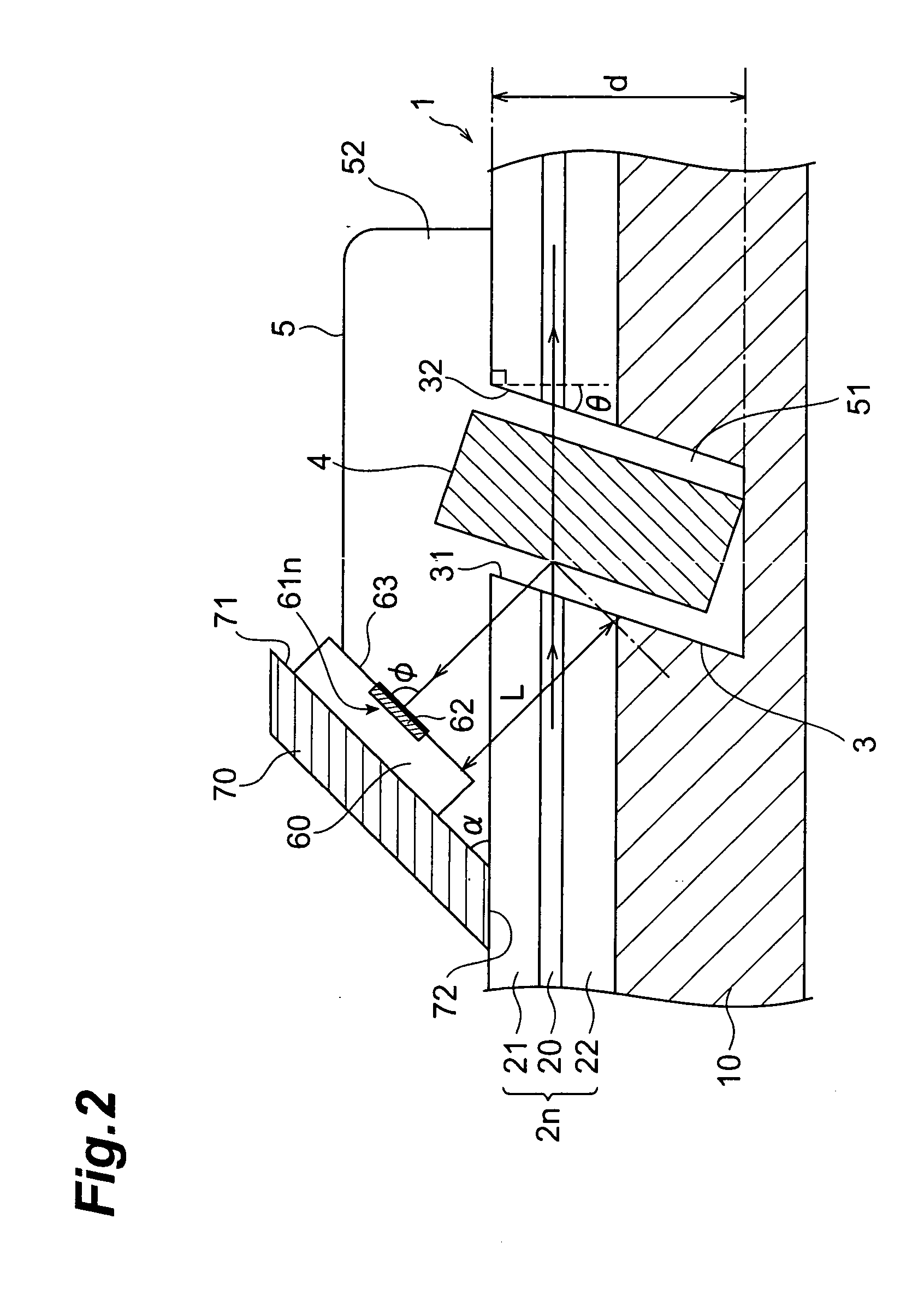
Figure 3
Abstract
Description
TECHNICAL FIELD
[0001] The present invention relates to an optical waveguide module having an optical waveguide formed on a substrate. BACKGROUND ART
[0002] In an optical circuit, which makes use of an optical waveguide such as an optical fiber or planar optical waveguide, it is sometimes desirable to control the optical intensity of signal light to a suitable value, such as keeping the optical intensity constant for signal light transmitted through optical waveguides. In such a case, the optical intensity of the signal light is monitored in the optical circuit, and sometimes the optical intensity is also controlled on the basis of the results of this monitoring. DISCLOSURE OF THE INVENTION
[0003] This monitoring of the optical intensity of signal light used to be accomplished by providing an optical coupler on an optical waveguide and splitting part of the signal light. With this method, an optical coupler is provided at a specific location along the optical waveguide, a few percen...
Examples
first embodiment
[0032]FIG. 1 is a plan view of a structure of an optical waveguide module in accordance with the present invention. The optical waveguide module comprises an optical circuit 1 which are constituted of a substrate 10, and 8 optical waveguides 21-28 (8 channels) disposed on the substrate 10. In this embodiment, for the optical waveguides 21-28, an optical waveguide of planar optical waveguide type, which are formed on the substrate 10, are employed.
[0033] Each of the optical waveguides 21-28 is formed parallel to each other at regular intervals along a predetermined optical transmission direction (the direction indicated by the arrowheads in FIG. 1) from input end 11 toward output end 12 of a planar optical waveguide type optical circuit 1. Also, at a predetermined portion with respect to the optical transmission direction of the planar optical waveguide type optical circuit 1, a groove 3, which crosses the optical waveguides 21-28, is formed.
[0034] Inside the groove 3, a reflection ...
fourth embodiment
[0121]FIG. 13 is a cross sectional view showing a structure of cross section of the optical waveguide module along the direction of the optical axis of an optical waveguides 2n (n=1−8). In FIG. 13, a portion including a groove 3, a reflection filter 4 and photodetector array 85 is shown enlarged. Also, in the constitution shown in FIG. 13, the planar optical waveguide type optical circuit 1 including optical waveguides 2n comprised of the lower clad 22, the core 20 and the upper clad 21, the groove 3, the reflection filter 4 and the filler resin 5 are the same as those in the constitution in FIG. 2.
[0122] The optical waveguide module according to this embodiment has almost the same constitution as that of the first embodiment shown in FIG. 1 and FIG. 2. Hence, in this embodiment, the plan view is omitted. To be more specific, the optical waveguide module according to this embodiment is different from the first embodiment in the constitution of the sub-mounting substrate or the like...