
Motorized adjustable workstation
Patent Information
- Authority / Receiving Office
- US · United States
- Current Assignee / Owner
- Publication Date
- 2005-07-14
- Estimated Expiration
- Not applicable · inactive patent
Smart Images
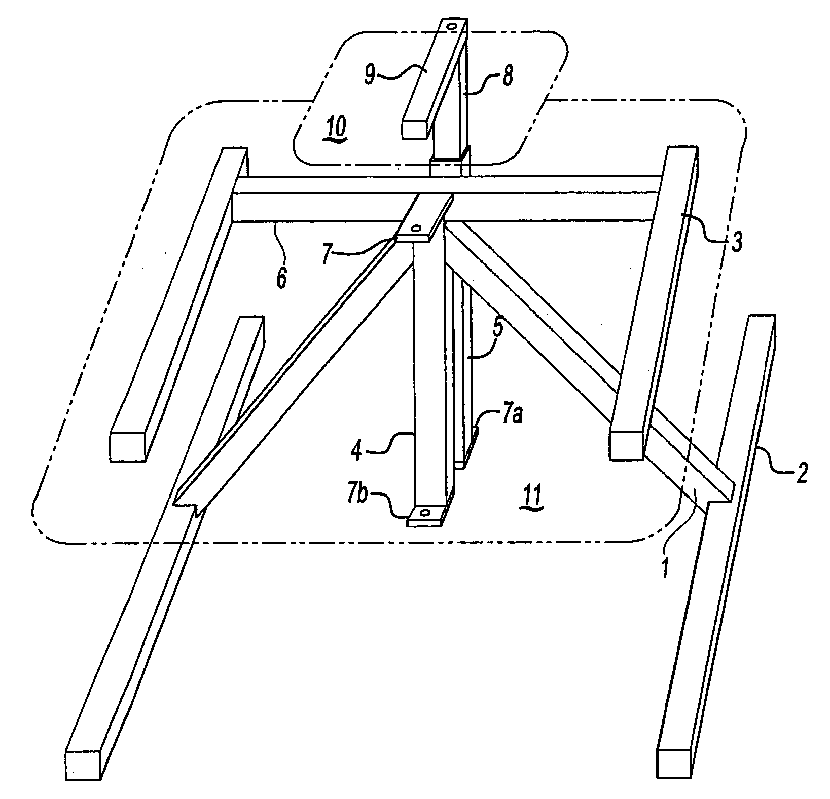
Figure 1 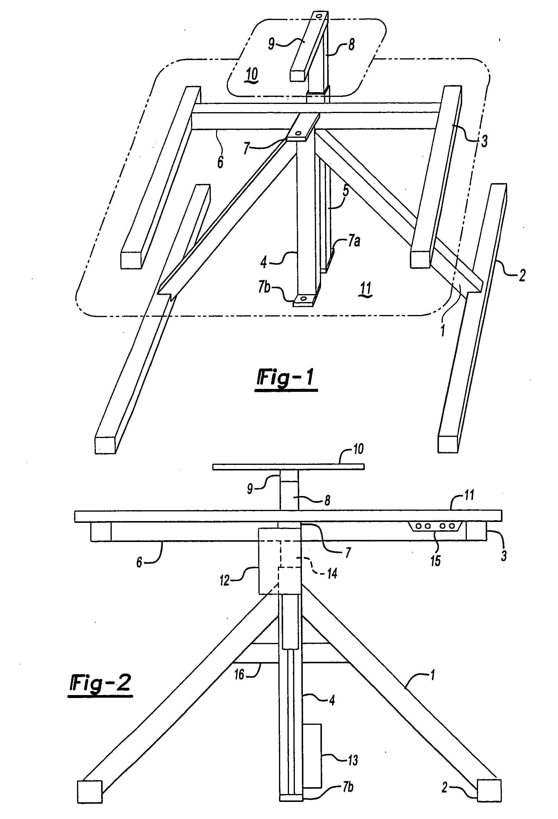
Figure 2 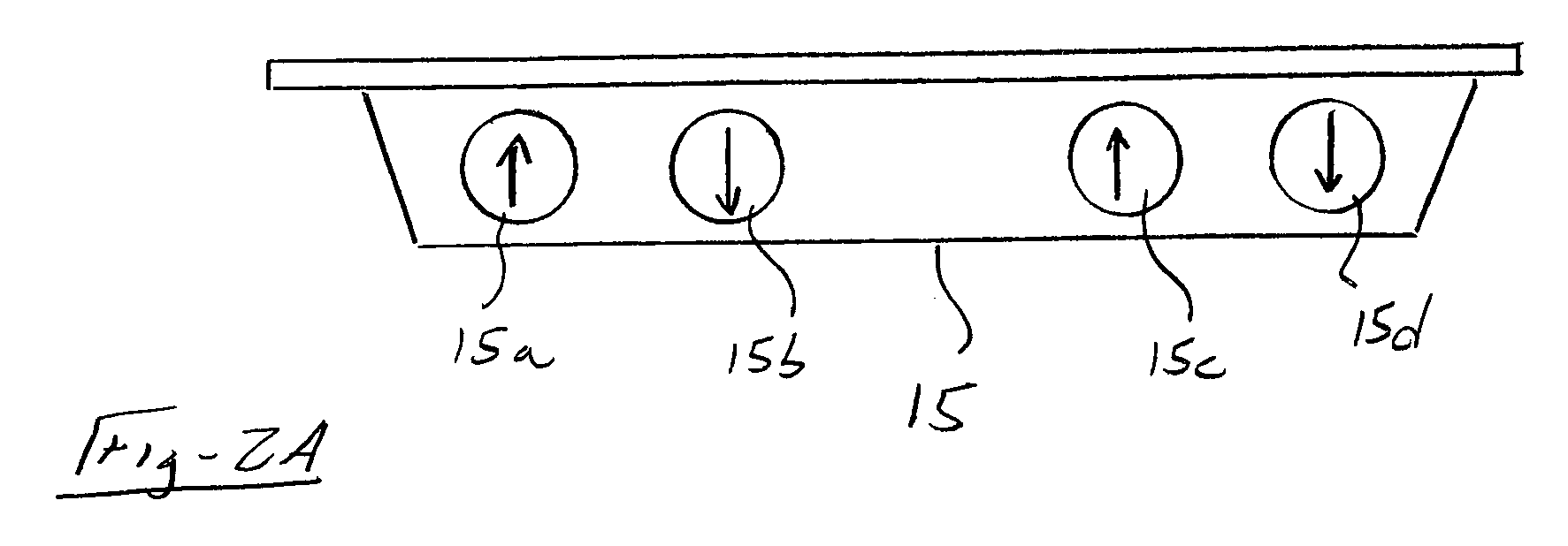
Figure 3
Abstract
Description
RELATED APPLICATIONS
[0001] This application is a continuation-in-part of U.S. patent application Ser. No. 10 / 272,730 filed Oct. 15, 2002, which claims priority of U.S. Provisional Patent Application Ser. No. 60 / 330,331 filed Oct. 19, 2001.STATEMENT REGARDING FEDERALLY SPONSORED RESEARCH OR DEVELOPMENT
[0002] U.S. Department of Education SBIR grant #ED-99-PO-4679, “Development of an ergonomic computer workstation environment” funded research in local schools on the need for adjustable ergonomic computer workstation environments. We found over 90% of students in any given age group or grade did not fit the computer workstations available in their school. It was demonstrated that the MOTORIZED ADJUSTABLE WORKSTATION invention, with a motor driven work surface and a motor driven monitor lift, had enough range of movement to ergonomically adjust to accommodate 6-year-old first graders to 6′3″ high school students.BACKGROUND OF THE INVENTION
[0003] This invention relates to the field of ...
Examples
Embodiment Construction
[0026] The present invention relates to a new and improved motorized adjustable workstation. The invention can be utilized in any environment where people would benefit from an adjustable work surface and / or adjustable monitor lift. It is particularly suited for computer workstation solutions.
[0027] The preferred embodiment of the workstation as shown in FIGS. 1-3, consists of a base made of tubing that generally includes two feet 2 and two interconnected legs 1 forming a stable bipod that intersects and supports a vertical main drive tube 4 with a means of adjoinment, that approximate 45+ / −degree angles, to form a stable, sturdy structure that raises the bending moment of the main drive tube 4 a significant distance above the floor.
[0028] A main linear actuator 12 (see FIG. 2) raises a main drive shaft 14 slidably disposed within the tube 4 and which supports a bow back 6 with its attached arms 3 and thereby supports a main work surface 11. A monitor lift attachment tube 17 (see ...