
Displacement pump with variable volume flow
a variable-volume flow, displacement pump technology, applied in the direction of rotary or oscillating piston engines, engine lubrication, rotary piston engines, etc., can solve the problems of inability to arbitrarily reduce the diameter of the gear ring running set, the outer diameter of the variable pump is too large, and the design space of the variable pump is reduced. , to achieve the effect of reducing hydrostatic losses, reducing hydrostatic losses, and compactness of the variable-volume pump according to
Patent Information
- Authority / Receiving Office
- US · United States
- Current Assignee / Owner
- Publication Date
- 2005-09-29
- Estimated Expiration
- Not applicable · inactive patent
Smart Images
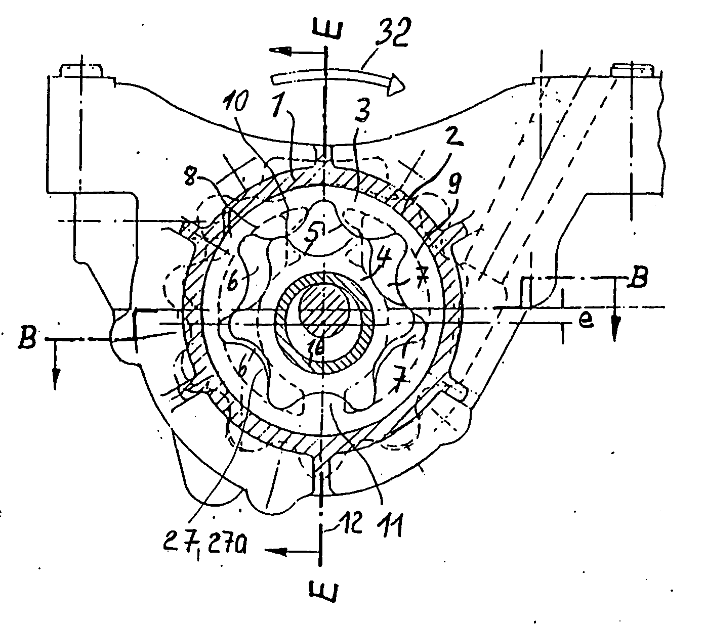
Figure 1 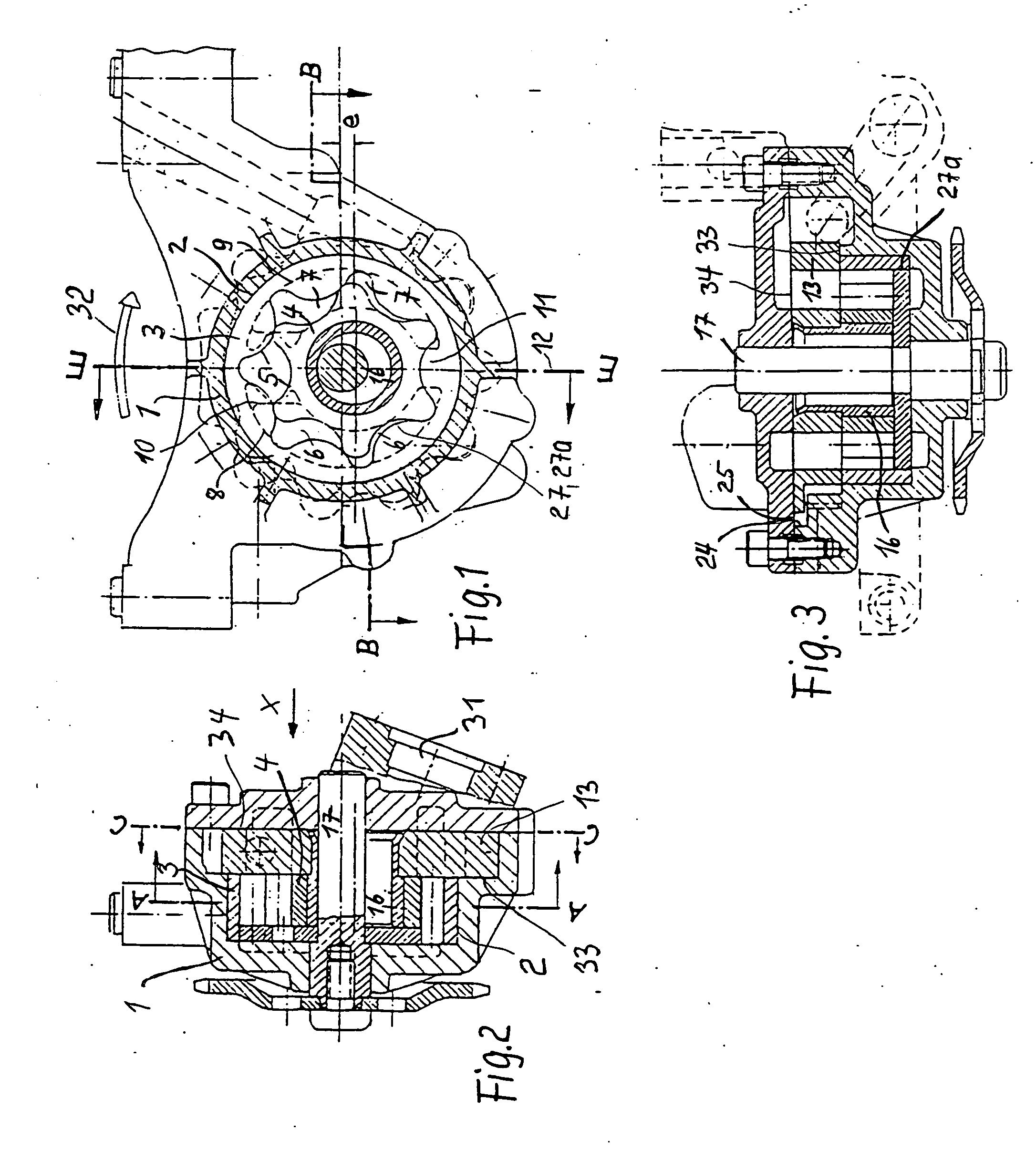
Figure 2 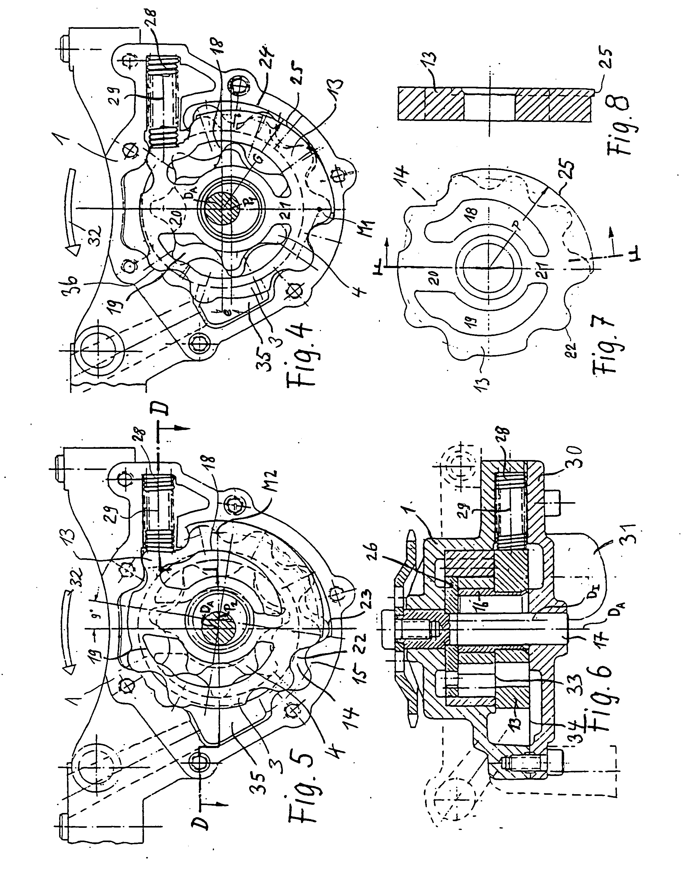
Figure 3
Abstract
Description
FIELD OF THE INVENTION
[0001] The invention relates to displacement pumps, in particular internal-axle gear pumps, but also wing cell pumps or for example also pendulum slider pumps, whose volume flow can be varied according to requirement, i.e. can be adjusted. The pumps in accordance with the invention are preferably used as lubricant oil pumps for internal combustion engines, wherein the internal combustion engine itself preferably drives the lubricant oil pump in question. The internal combustion engine can in particular be a drive motor, preferably a piston motor, of a vehicle. The specific volume flow, i.e. the volume flow delivered per revolution of a delivery wheel of the pump, can preferably be adjusted continuously. The displacement pumps can also be advantageously used as supply pumps for automatic transmissions in vehicles and when used in this way are also preferably driven by the drive motor of the vehicle in question. Although the displacement pump of the invention, w...
Examples
Embodiment Construction
[0029] For explaining the function in the individual figures, the rotational direction of the running set shall be in the indicated direction of the arrow 32, such that the respective suction and pressure side in accordance with the expanding and compressing delivery cells of the teeth is clearly provided. In the cover 30, the suction support 31 is arranged on the suction side of the running set, on which side the variable spring 28 can also be seen. Thus, the spaces of the variable spring 28 and the rolling cylinders 24 and 25, and the sections of the toothing shown on the right of the image in FIGS. 4, 5, 6 and 7 between the variable plate 13 and the casing 1 are under suction pressure, since the variable plate 13 is fitted in between the cavern base 33 of the casing and the casing-cover partition line, forming an axial seal but able to move. The pressure space 35, which is hydraulically connected to the compressing delivery cells of the gear ring running set with the minimum poss...