
Hydraulic shock absorber
a technology of shock absorber and shock absorber, which is applied in the direction of shock absorber, damper-spring combination, vibration damper, etc., can solve the problem of increasing the damage force generated by the main valv
Patent Information
- Authority / Receiving Office
- US · United States
- Patent Type
- Applications(United States)
- Current Assignee / Owner
- Publication Date
- 2005-12-01
Smart Images
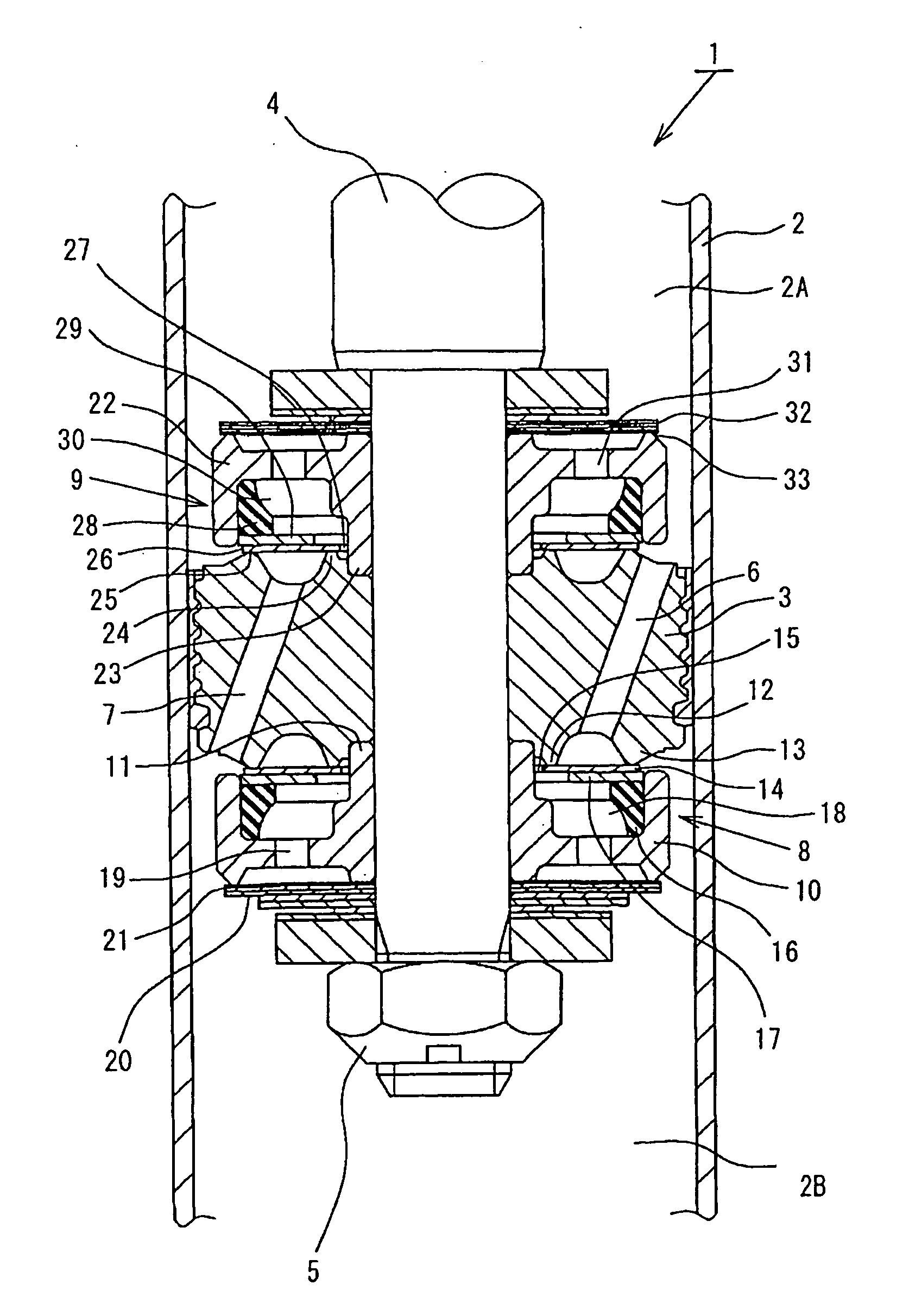
Figure 1 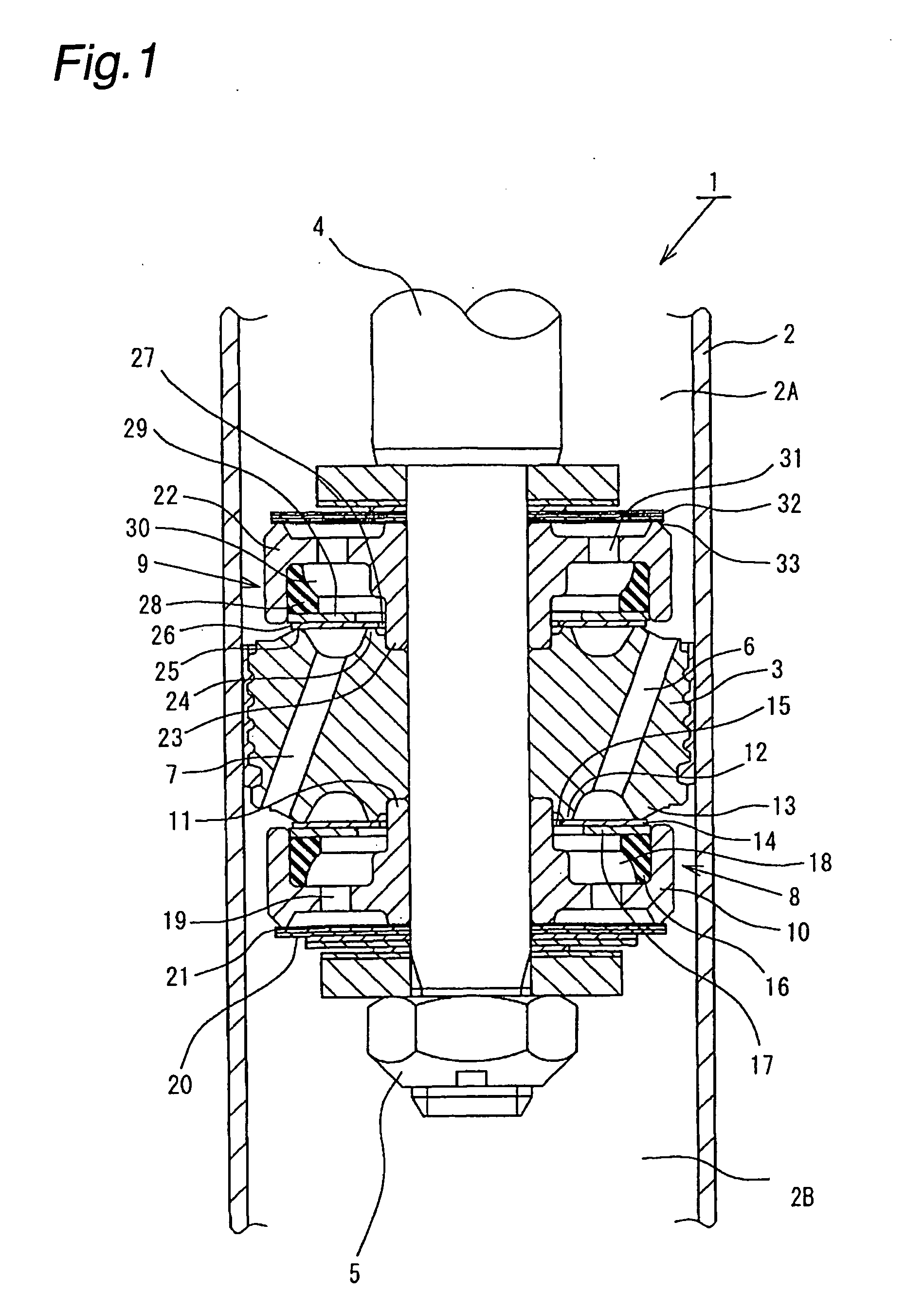
Figure 2 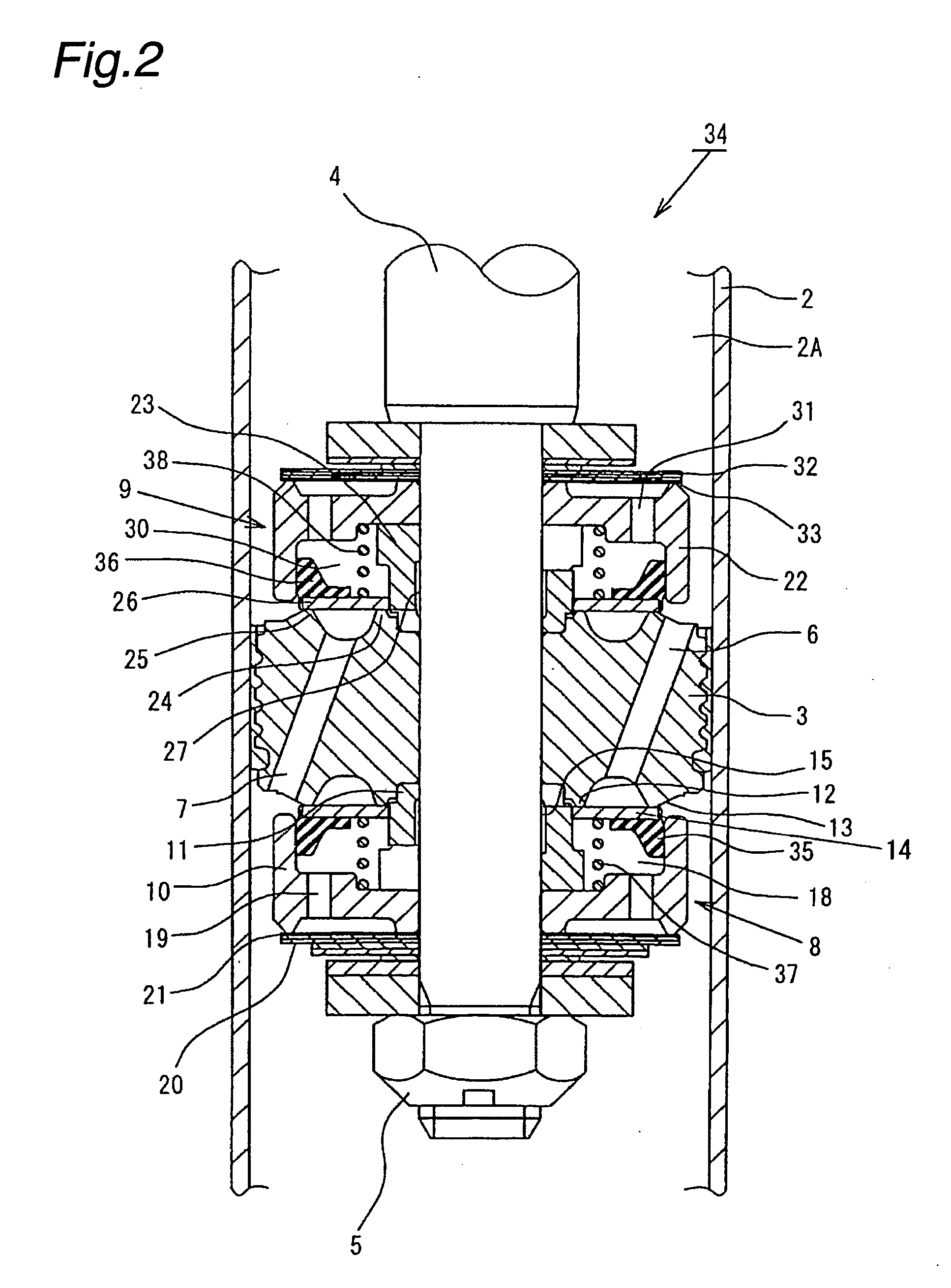
Figure 3
Abstract
Description
BACKGROUND OF THE INVENTION
[0001] The present invention relates to a hydraulic shock absorber suitable for use in a suspension system of a vehicle, for example, an automobile.
[0002] In general, a cylinder type hydraulic shock absorber attached to a suspension system of a vehicle, e.g. an automobile, includes a cylinder having a hydraulic fluid sealed therein. A piston is slidably fitted in the cylinder. The piston is connected with a piston rod to form a piston assembly. The piston assembly is provided with damping force generating mechanisms each including a hydraulic fluid passage, an orifice, a disk valve, etc. The hydraulic fluid is induced to flow through the hydraulic fluid passage by sliding movement of the piston in the cylinder caused by the stroke of the piston rod. The flow of the hydraulic fluid is controlled by the orifice and the disk valve to generate damping force. In a low speed region of the piston speed, damping force is generated by the orifice. In a high pisto...
Examples
first embodiment
[0054] The above-described arrangement offers advantageous effects similar to those in the foregoing Further, because the main disk valves 14 and 26 and the oil seals 35 and 36 are secured to each other, respectively, sealing performance between these members can be enhanced. Hence, the sealing properties of the back-pressure chambers 18 and 30 can be improved. In addition, it is possible to improve the assembleability of these constituent members to the extension and compression damping force generating mechanisms 8 and 9.
[0055] Next, a third embodiment of the present invention will be described with reference to FIG. 3. It should be noted that in the third embodiment, members or portions that are similar or equivalent to those of the foregoing first embodiment are denoted by the same reference numerals as those used in the first embodiment, and only the portions in which the third embodiment differs from the first embodiment will be explained in detail.
[0056] In a hydraulic shoc...
fourth embodiment
[0059] In a hydraulic shock absorber 42 the main disk valves 14 and 26 are flexible and clamped at their inner peripheral portions between the respective valve members 10 and the piston 3. The main disk valves 14 and 26 open by deflecting. A notched disk 43 as shown in FIG. 6 and a blocking disk 45 as shown in FIG. 5 are stacked in the order mentioned at the side of the main disk valve 14 closer to the extension hydraulic fluid passage 6 (i.e. at the upstream side of the main disk valve 14). Similarly, a notched disk 44 as shown in FIG. 6 and a blocking disk 46 as shown in FIG. 5 are stacked in the order mentioned at the side of the main disk valve 26 closer to the compression hydraulic fluid passage 7 (i.e. at the upstream side of the main disk valve 26). As shown in FIG. 7 or 8, the main disk valves 14 and 26 have circumferentially extending arcuate openings 47 and 48 provided in respective portions closer to the inner peripheries thereof. The notched disks 43 and 44 are each pro...
third embodiment
[0061] The above-described arrangement offers advantageous effects similar to those in the foregoing Further, in this embodiment, back-pressure chamber inlet passages (upstream orifices) for controlling a very small amount of flow are formed by the T-shaped notches 49 and 50 of the notched disks 43 and 44. Accordingly, a desired flow path area when the main disk valve 14 (26) is closed can be set easily by appropriately varying the width, thickness and number of notches 49 (50). Thus, it becomes easy to control the dimensional accuracy and hence possible to obtain stable damping force having minimal variations.
[0062] It should be noted that in the above-described fourth embodiment, the notched disks 43 and 44 may be integrated with the main disk valves 14 and 26, respectively, so that when the main disk valve 14 (26) opens, the notched disk 43 (44) separates from the blocking disk 45 (46), thereby increasing the effective flow path area of the back-pressure chamber inlet passage.
[...