
Laser scanning system for object monitoring
a scanning system and object technology, applied in the field of optical systems for monitoring the motion, can solve the problems of inability to detect objects, and inability to detect objects, and achieve the effect of rapid high-resolution data
Patent Information
- Authority / Receiving Office
- US · United States
- Patent Type
- Applications(United States)
- Current Assignee / Owner
- Publication Date
- 2006-03-23
- Estimated Expiration
- Not applicable · inactive patent
Smart Images
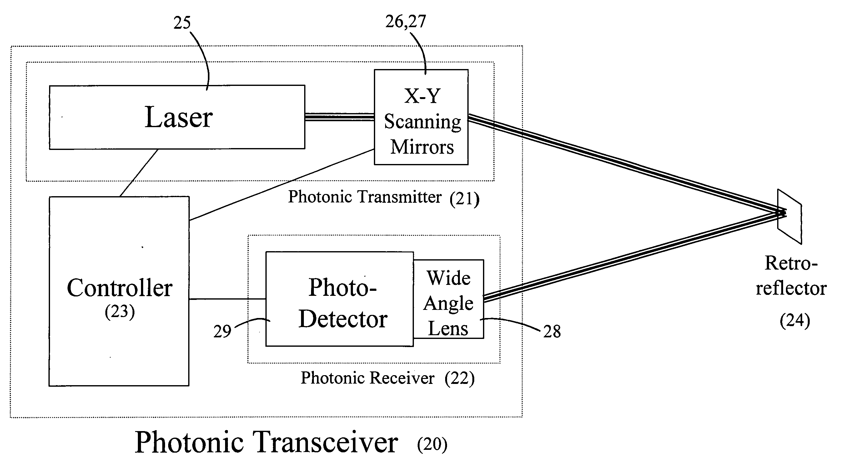
Figure 1 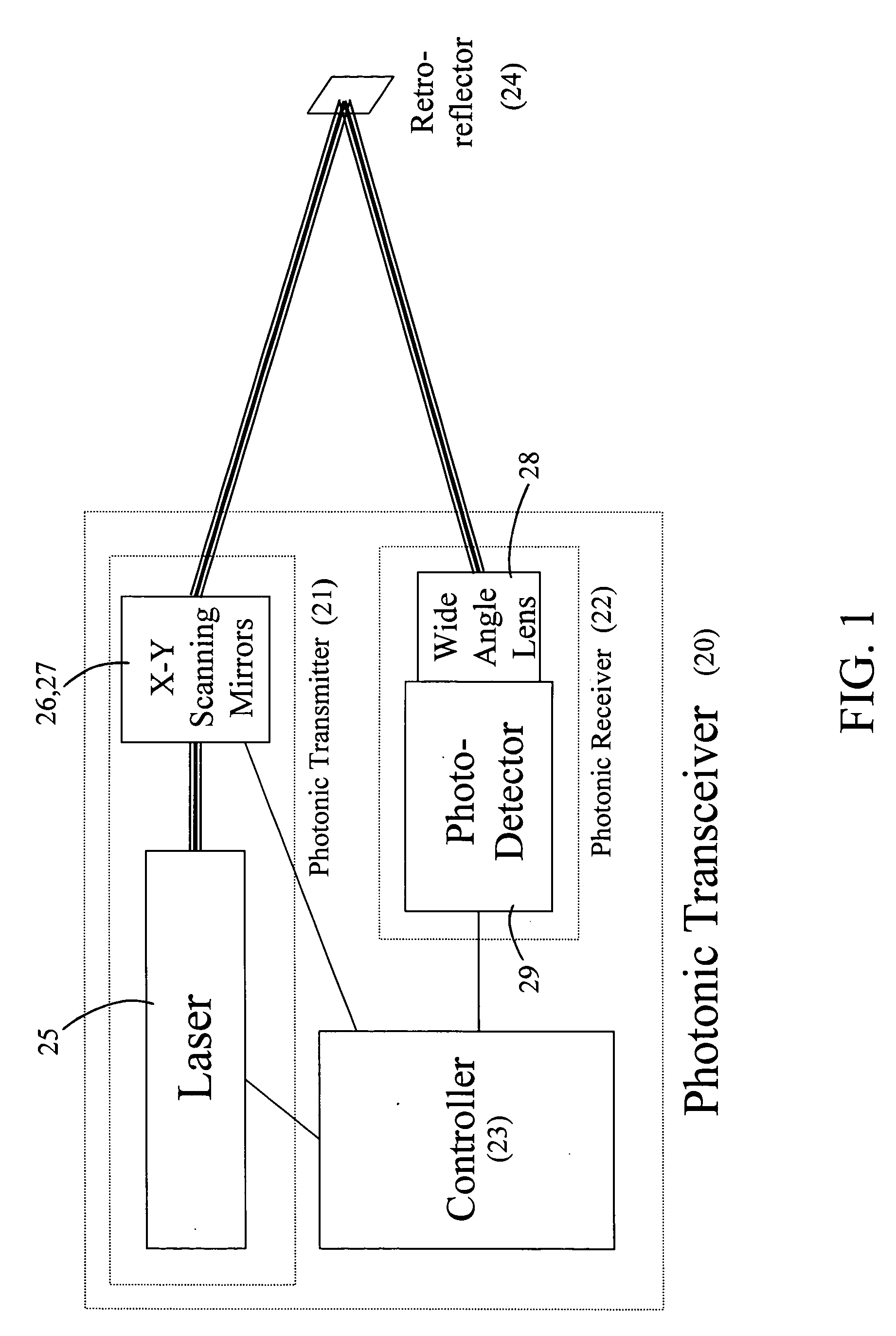
Figure 2 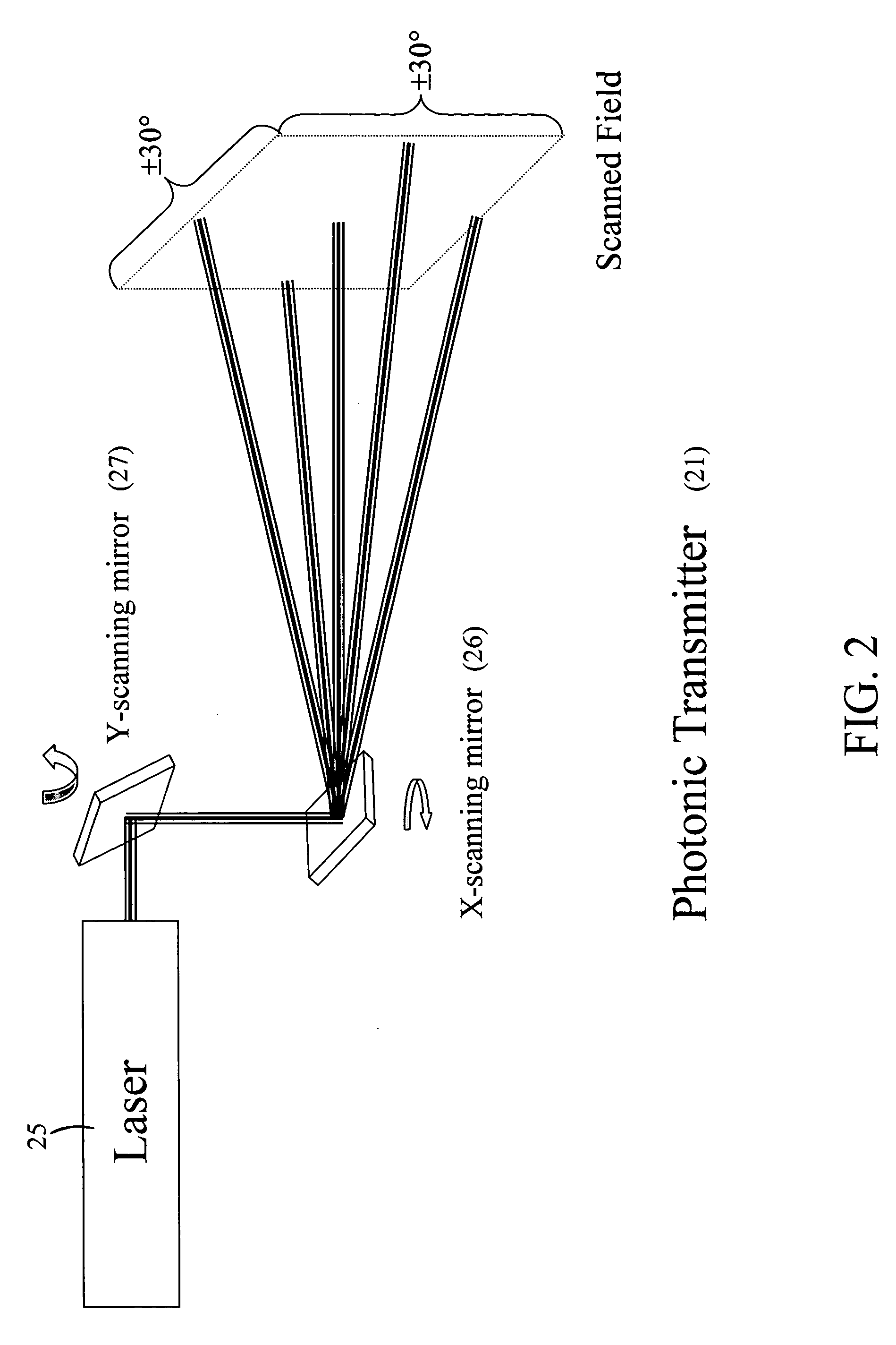
Figure 3
Abstract
Description
STATEMENT REGARDING FEDERALLY SPONSORED RESEARCH OR DEVELOPMENT
[0001] The United States Government has rights in this invention pursuant to Contract No. DE-AC05-00OR22725 between the United States Department of Energy and UT-Battelle, LLC.BACKGROUND OF THE INVENTION
[0002] 1. Field of the Invention
[0003] The invention is related to optical systems for monitoring the motion of objects. In particular, increased information bandwidth is achieved in a laser scanning transceiver system through the use of a noncommon collection path for the return light from retroreflectors located on the monitored objects.
[0004] 2. Description of Prior Art
[0005] Wireless monitoring systems, whether based on optical or radio frequency (RF) technologies, are used in many applications where it is desired to monitor the movement of large structures, vehicles or groups of stationary objects. The purpose is to measure the position and / or disturbance to that position of tags located on objects, and to do so...
Examples
Embodiment Construction
[0052] In FIG. 1, the laser scanning system of our invention includes at least one photonic transceiver 20 that comprises a photonic transmitter 21, a photonic receiver 22, and a controller 23. The photonic transmitter 21 directs laser light to one or more retroreflecting targets 24. The photonic transmitter 21 shown in FIG. 2 includes a means for steering the laser beam to a multiplicity of targets in the scanned field. The steering range is generally limited to ±30° from normal, in both the horizontal and vertical directions, and is accomplished via galvanometer controlled rotating mirrors 26, 27. The device used for rotating the mirrors 26, 27 may be a Cambridge Technology 2-D scanning mirror device model 6350, for example. Once the laser beam has been directed to a retroreflective target, the target returns a diffuse cone of light 30 as shown in FIG. 3. Depending upon the characteristics of the retroreflective target 24, the distribution of returned light energy may vary as a fu...