
Acceleration Sensor
Patent Information
- Authority / Receiving Office
- US · United States
- Current Assignee / Owner
- Publication Date
- 2008-04-17
- Estimated Expiration
- Not applicable · inactive patent
Smart Images
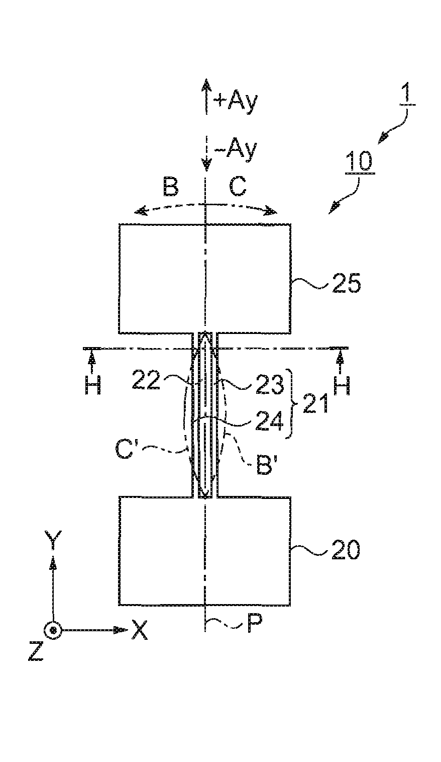
Figure 1 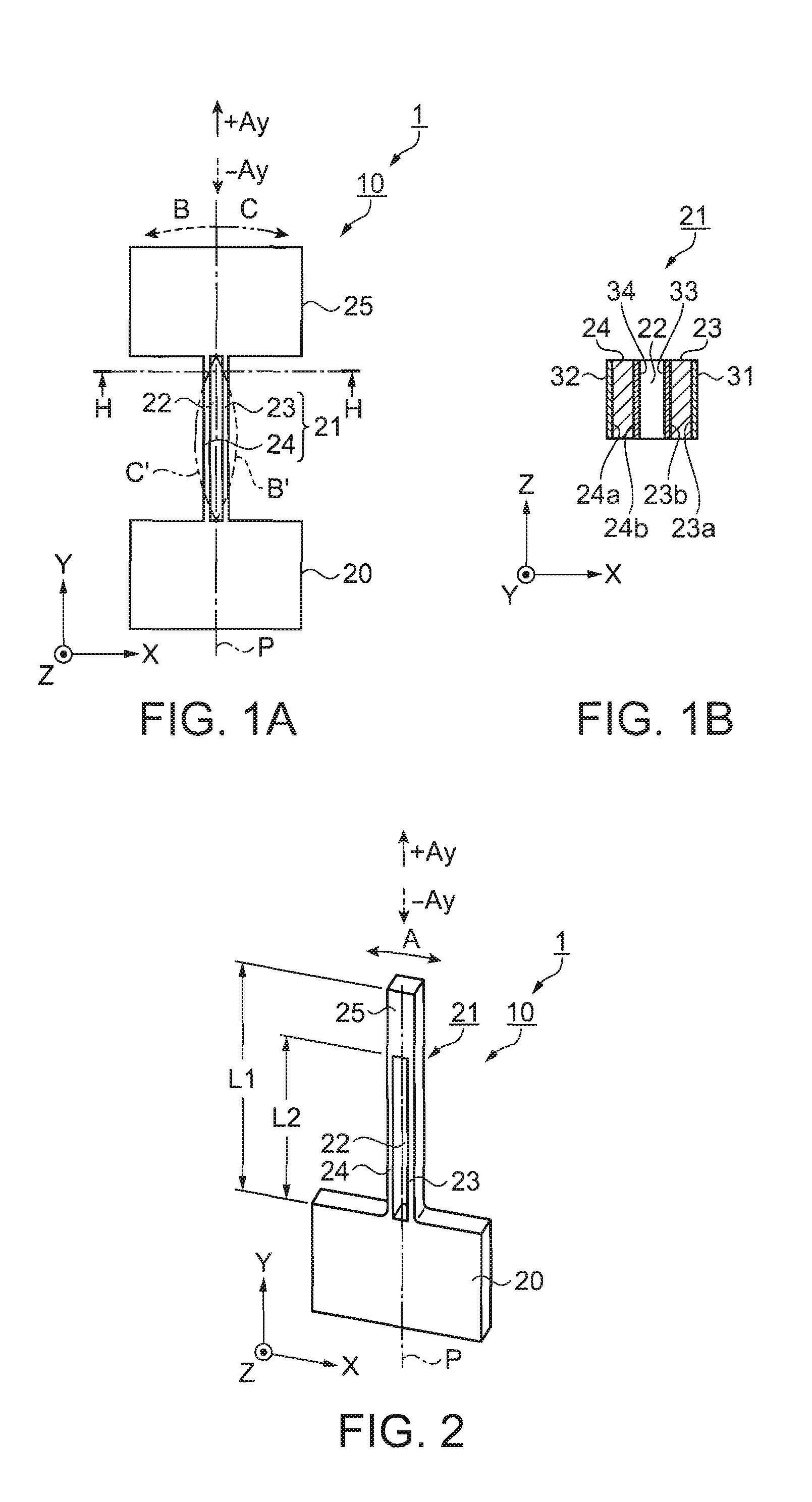
Figure 2 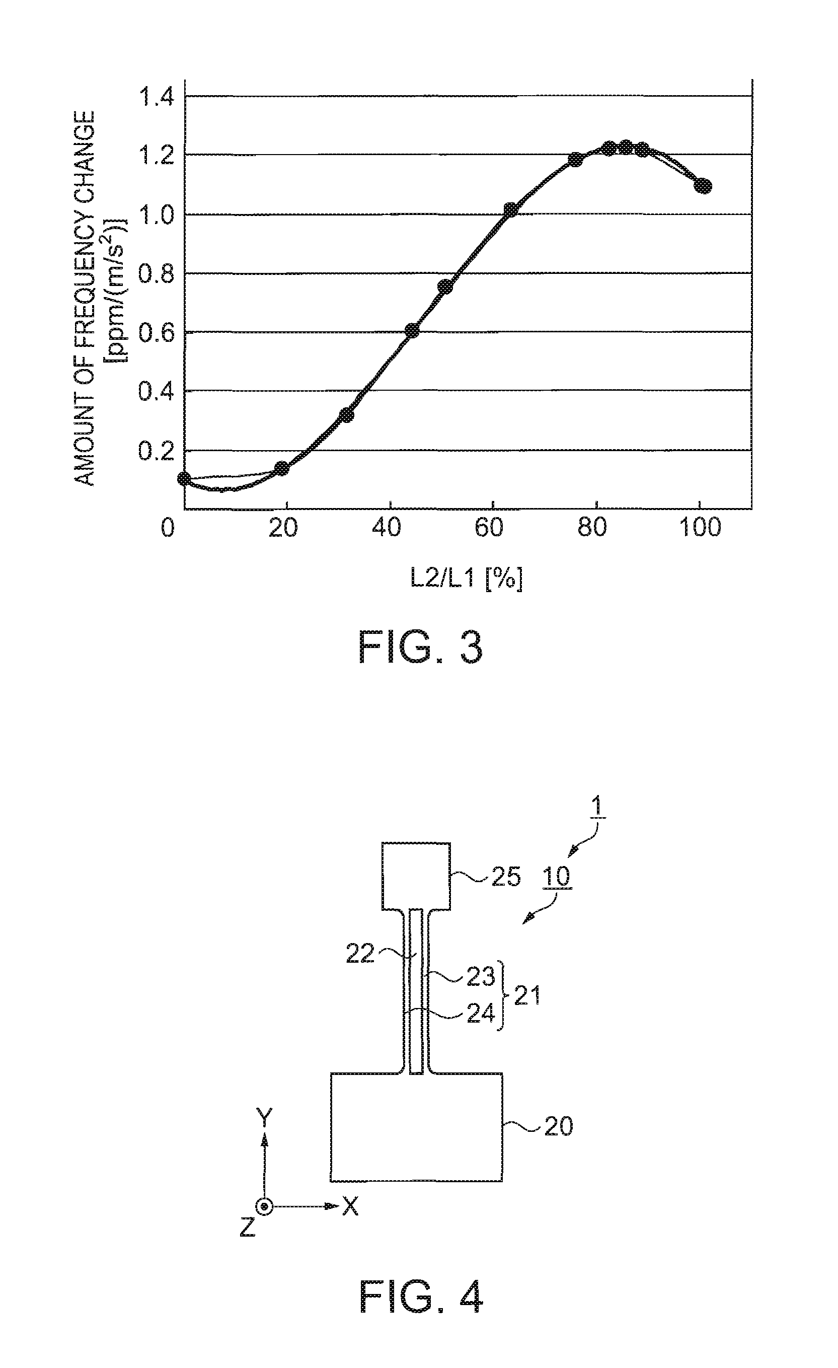
Figure 3
Abstract
Description
BACKGROUND
[0001] 1. Technical Field
[0002] The present invention relates to an acceleration sensor that detects the frequency change of a vibrating body when an acceleration is impressed.
[0003] 2. Related Art
[0004] A known acceleration sensor includes a spiral spring, a resonator, and is formed with silicon having a vibrating mass suspended to a frame, where acceleration is detected based on a frequency change of a resonator, and where the spiral spring, the frame, and the vibrating mass are formed by structuring the silicon platelet. JP-A-6-43179 (page 3; FIG. 1) is an example of such related art.
[0005] Another known acceleration sensor includes: a cantilever, one end thereof anchored on a silicon wafer substrate, the other end thereof being a resilient free end; a piezoelectric element film formed on a surface of the cantilever; a piezoelectric resonator formed including metallic electrodes formed on both sides of the piezoelectric element film and a weight fixed to the free end of the ...
Examples
first embodiment
[0071]FIGS. 1A and 1B show an example of an acceleration sensor according to the first embodiment, where FIG. 1A is a front elevational view thereof, and FIG. 1B is a sectional view of a section H-H in FIG. 1A. Referring now to FIG. 1A, an acceleration sensor 1 is formed with a vibrating body 10 that includes: a base 20 anchored to an un-illustrated pedestal; and an oscillating arm 21 extended out like a beam from the side surface of the base 20 and oscillates transversally in a planer direction at a predetermined resonant frequency.
[0072]The vibrating body 10 is formed with a piezoelectric material. Piezoelectric materials may include materials such as lead titanate (PbTiO3), lead titanate zirconate (PZT; registered trademark), zinc oxide (ZnO), and quartz. This embodiment exemplifies the usage of high-Q quartz that excels in temperature-frequency characteristics.
[0073]The vibrating body 10 is formed with a z-cut expanding in an x-y plane, and the oscillating arm 21 thereof extends...
first modification
[0096]An acceleration sensor according to a first modification of the first embodiment will now be described with reference to drawings. The first modification is peculiar in that the vibrating body has a single anchor structure and oscillates linearly and transversally. FIG. 2 is a perspective view illustrating a structure of the acceleration sensor according to the first modification. Referring to FIG. 2, the vibrating body 10 functioning as an acceleration sensor has the same configuration as that of the first embodiment (refer to FIGS. 1A and 1B), except for the added mass 25. The detection unit 35 is provided as an extension of the oscillating arm 21, and the through hole 22 divides the vibrating arm 21 into the oscillating blocks 23 and 24.
[0097]The excitation electrodes 31 to 34 shown in FIGS. 1A and 1B are disposed on the lateral surfaces of the oscillating blocks 23 and 24. If the oscillation circuit inputs excitation signals to the excitation electrodes 31 through 34, wher...
second modification
[0104]An acceleration sensor according to a second modification of the first embodiment will now be described with reference to drawings. The second modification is peculiar in that the free end of the oscillating arm is provided with an added mass which allows the linear and transversal oscillation. Components that are different from that of the aforementioned first embodiment (refer to FIGS. 1A and 1B) will mainly be described. Like reference numerals designate like structure in the first embodiment.
[0105]FIG. 4 is a front elevational view illustrating a vibrating body according to this modification. Referring to FIG. 4, the vibrating arm 21 of the vibrating body 10 extends vertically in the y-axis direction as a beam, from the center of one side of the base 20. A through hole 22 is opened in the center of the width direction (x-axis) of the vibrating arm 21, extending along longitudinal direction (y-axis), penetrating through in the thickness direction (z-axis).
[0106]The through ...