
Electro-wetting display panel
Patent Information
- Authority / Receiving Office
- US · United States
- Current Assignee / Owner
- Publication Date
- 2009-07-23
- Estimated Expiration
- Not applicable · inactive patent
Smart Images
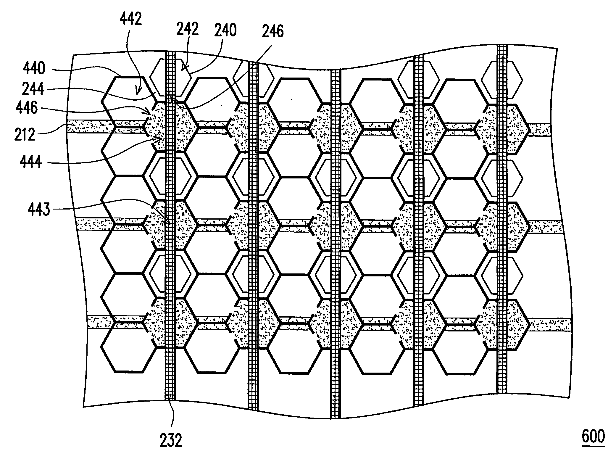
Figure 1 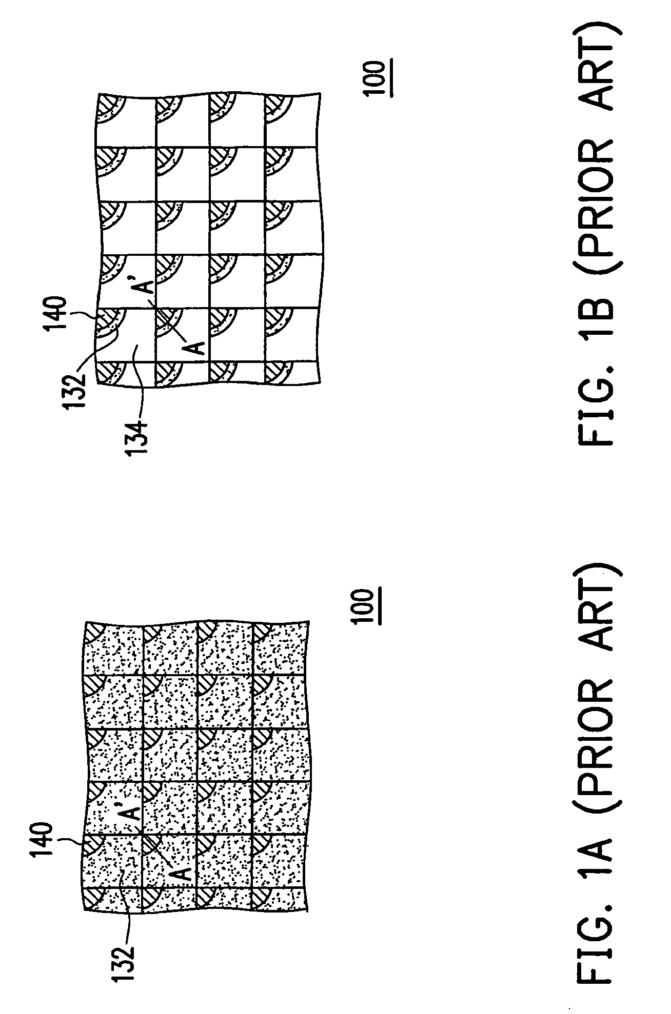
Figure 2 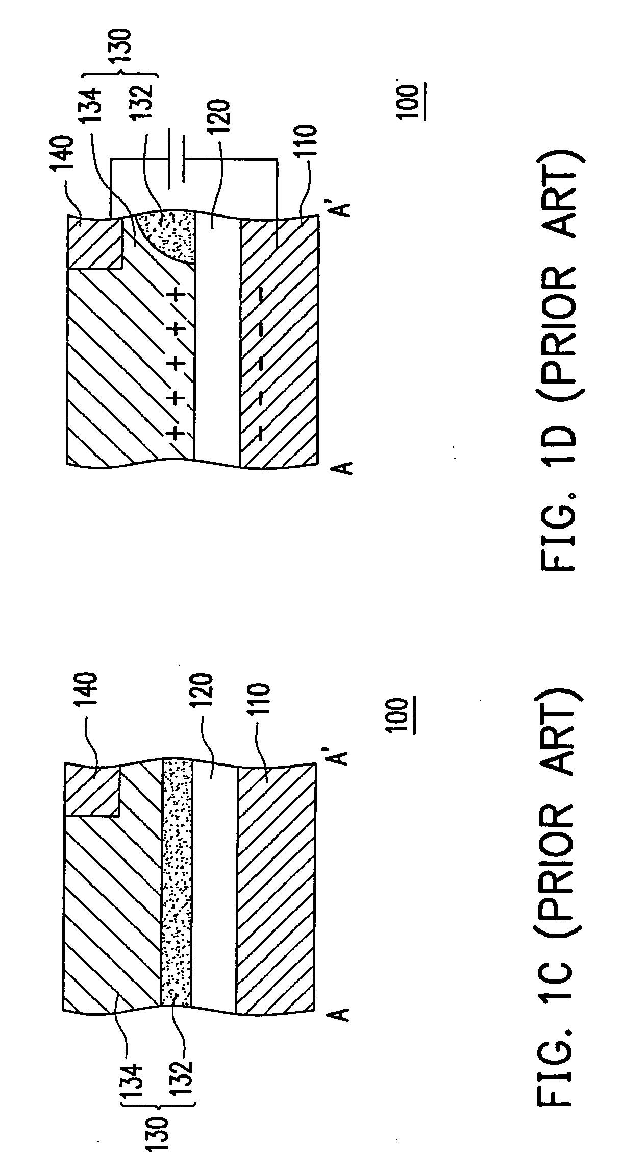
Figure 3
Abstract
Description
CROSS-REFERENCE TO RELATED APPLICATION
[0001] This application claims the priority benefit of Taiwan application serial no. 97102336, filed on Jan. 22, 2008. The entirety of the above-mentioned patent application is hereby incorporated by reference herein and made a part of this specification.BACKGROUND OF THE INVENTION
[0002] 1. Field of the Invention
[0003] The present invention generally relates to a display panel, in particular, to an electro-wetting display panel.
[0004] 2. Description of Related Art
[0005] Different types of display panels are constituted based on different display mechanisms. Presently, the most well-known display panels include liquid crystal display (LCD) panels, plasma display panels, field emission display panels, organic light emitting display panels, and electro-wetting display panels, wherein the development of electro-wetting display panels has become much focus because electro-wetting display panels have many advantages in performance and cost, for its high co...
Examples
first embodiment
[0025]FIG. 2A is a partial view of an electro-wetting display panel according to the first embodiment of the present invention, and FIG. 2B is a cross-sectional view of the electro-wetting display panel in FIG. 2A along line B-B′. Referring to FIG. 2A and FIG. 2B, in the present embodiment, the electro-wetting display panel 200 includes a first substrate 210, an insulator layer 220, a second substrate 230, a plurality of partitioning structures 240, and a plurality of electro-wetting display mediums 250. The second substrate 230 is located above the first substrate 210, and the insulator layer 220, the partitioning structures 240, and the electro-wetting display mediums 250 are disposed between the first substrate 210 and the second substrate 230, as shown in FIG. 2B.
[0026]As shown in FIG. 2A and FIG. 2B, the first substrate 210 has a plurality of first electrodes 212. In the present embodiment, the first electrodes 212 may be transparent electrodes, reflective electrodes, or transf...
second embodiment
[0034]FIG. 4A is a partial view of an electro-wetting display panel according to the second embodiment of the present invention, and FIG. 4B is a cross-sectional view of the electro-wetting display panel in FIG. 4A along line C-C′. Referring to FIG. 4A and FIG. 4B, the electro-wetting display panel 400 has similar structure as the electro-wetting display panel 200, wherein like reference numerals refer to like elements. The difference between the two electro-wetting display panels is that the electro-wetting display panel 400 has a partition 440 and the partition 440 is different from the partitioning structures 240 in the electro-wetting display panel 200. The insulator layer 220, the partition 440, and the electro-wetting display mediums 250 are disposed between the first substrate 212 and the second substrate 232, as shown in FIG. 4B. In addition, the dispositions of the first electrodes 212 and the second electrodes 232 of the electro-wetting display panel 400 are different from...
third embodiment
[0040]FIG. 6 is a partial View of an electro-wetting display panel according to the third embodiment of the present invention. Referring to FIG. 6, the structure of the electro-wetting display panel 600 is similar to that of the electro-wetting display panel 200 or 400, wherein like reference numerals refer to like elements. The difference between the electro-wetting display panel 600 and the electro-wetting display panel 200 or 400 is that the electro-wetting display panel 600 has a combined design of the partitioning structures in the electro-wetting display panel 200 and the partition in the electro-wetting display panel 400, as shown in FIG. 2A, FIG. 4A, and FIG. 6.
[0041]To be specific, when the electro-wetting display panel 600 is driven, the color fluid 252 in some of the pixel regions 242 is stored into the flow channels 244 through the aperture 246 according to the design of the partition structures 240, and the color fluid 252 in some of the pixel regions 442 is stored into...