
Method for producing ceramic-honeycomb-structure-molding die and method for producing ceramic honeycomb structure
a technology of structure and die, which is applied in the field of method for producing ceramic honeycomb structure, can solve the problems of deteriorating precision of width and depth of groove, affecting the use of tools, so as to prevent the breakage and warpage of rotating tools
Patent Information
- Authority / Receiving Office
- US · United States
- Patent Type
- Applications(United States)
- Current Assignee / Owner
- Publication Date
- 2010-02-25
Smart Images

Figure 1 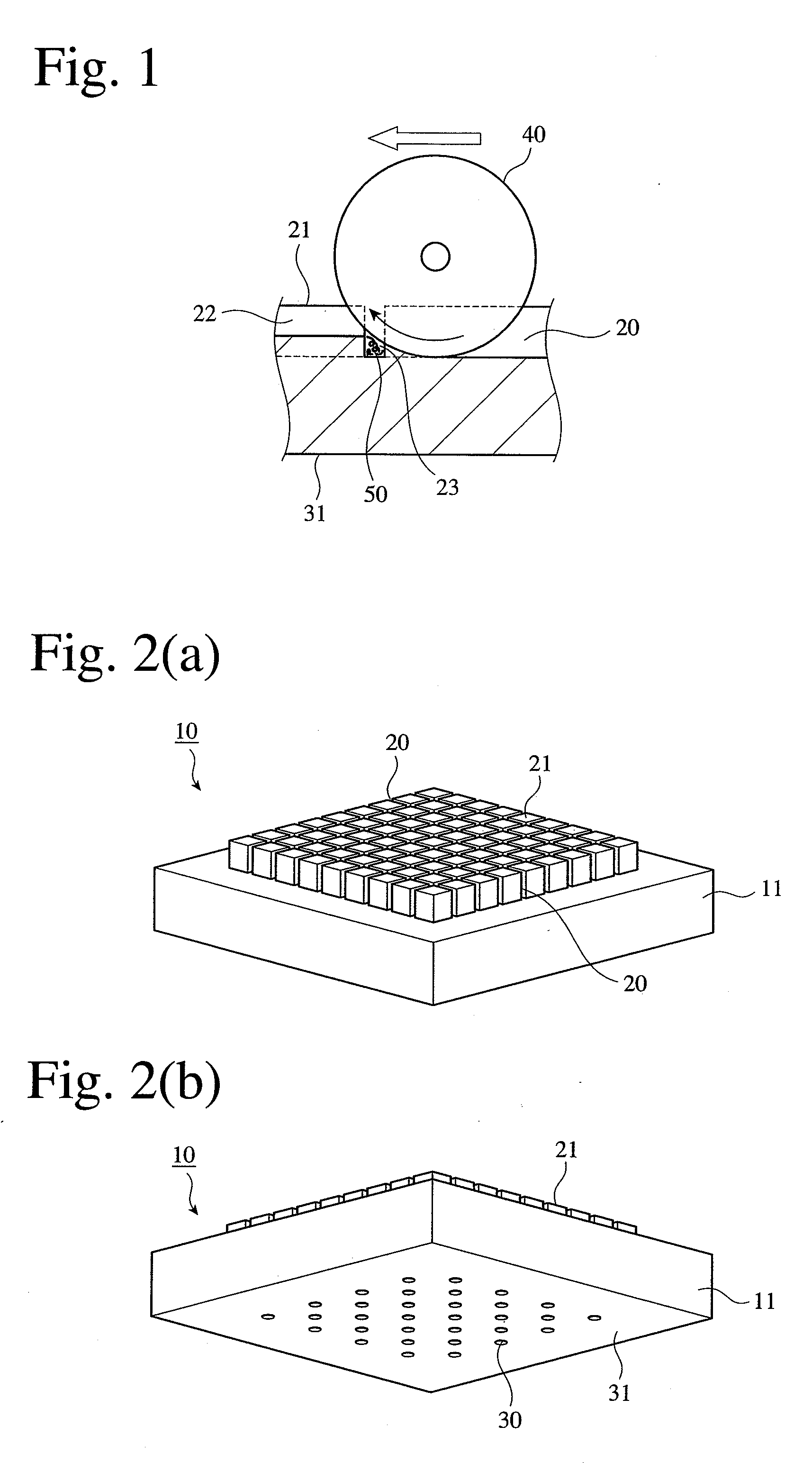
Figure 2 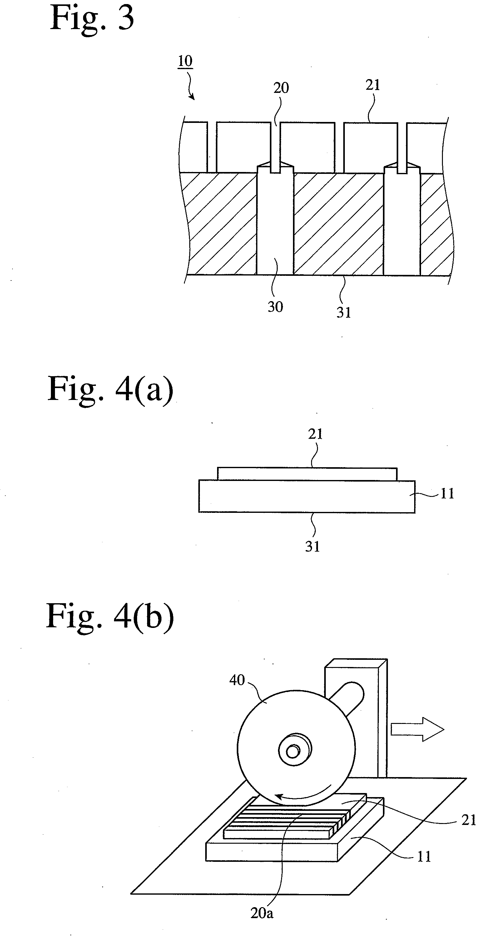
Figure 3
Abstract
Description
FIELD OF THE INVENTION
[0001] The present invention relates to a method for producing a die used for the extrusion molding of a ceramic honeycomb structure, and a method for producing a ceramic honeycomb structure.BACKGROUND OF THE INVENTION
[0002] A ceramic honeycomb structure (simply called “honeycomb structure” below) used as a filter for cleaning an exhaust gas, etc. is produced by extruding a moldable ceramic material through a honeycomb-structure-molding die (simply called “molding die”) to form a honeycomb molding, and drying and sintering it. As shown in FIGS. 2(a) and 2(b), the molding die 10 is formed from a die-forming work 11 having such a shape that a groove-having surface 21 projects, that moldable-material-supplying apertures 30 are formed in the die-forming work 11 such that they extend from an aperture-having surface 31, and that lattice-patterned grooves 20 are formed on a groove-having surface 21. As shown in FIG. 3, the moldable-material-supplying apertures 30 of the...
Examples
example 1
[0033](1) Formation of Moldable-Material-Supplying Apertures
[0034]Prepared was a die-forming work 11 made of alloy tool steel (JIS G4404), which had a projected groove-having surface 21 of 240 mm×240 mm, and a surface 31 of 260 mm×260 mm from which apertures were formed, as shown in FIG. 4(a). The die-forming work 11 was drilled with a cemented carbide drill having a diameter of 1.1 mm and a tip angle of 140° from the aperture-machining surface 31 to form apertures 30 as shown in FIG. 3.
[0035](2) Formation of First Grooves
[0036]The groove-having surface 21 was machined by a rotating tool 40 to form grooves 20. The tool 40 was a thin grinder disc having a thickness of 0.25 mm and a diameter of 100 mm. First, parallel grooves 20 as deep as 4 mm were formed by down-cutting (first pass). The second-pass machining was then conducted by up-cutting, such that the previously machined grooves 20 became 2.5 mm deeper, namely the depth of the machined grooves 20 became 6.5 mm. The diameter of ...