

Illumination device and display device
a technology which is applied in the field of illumination device and display device, can solve the problems of low utilization efficiency of light from the light source of the backlight, limited thickness, cost, etc., and achieve the effect of low cost, high efficiency and thin outpu
Patent Information
- Authority / Receiving Office
- US · United States
- Patent Type
- Applications(United States)
- Current Assignee / Owner
- Publication Date
- 2010-05-20
Smart Images
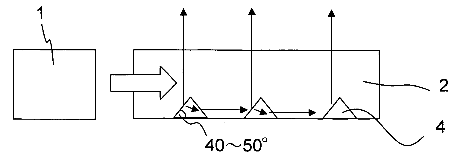
Figure 1 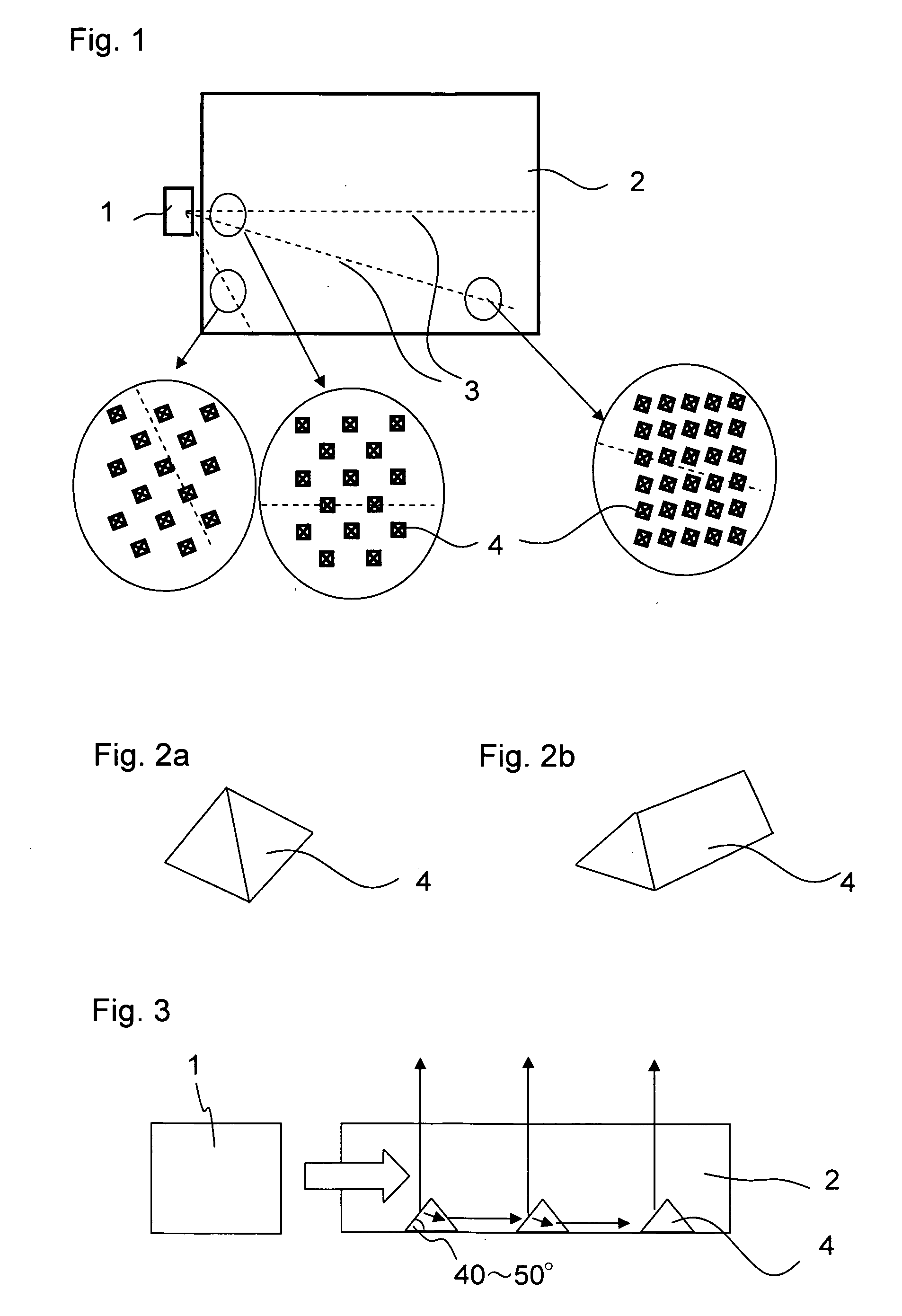
Figure 2 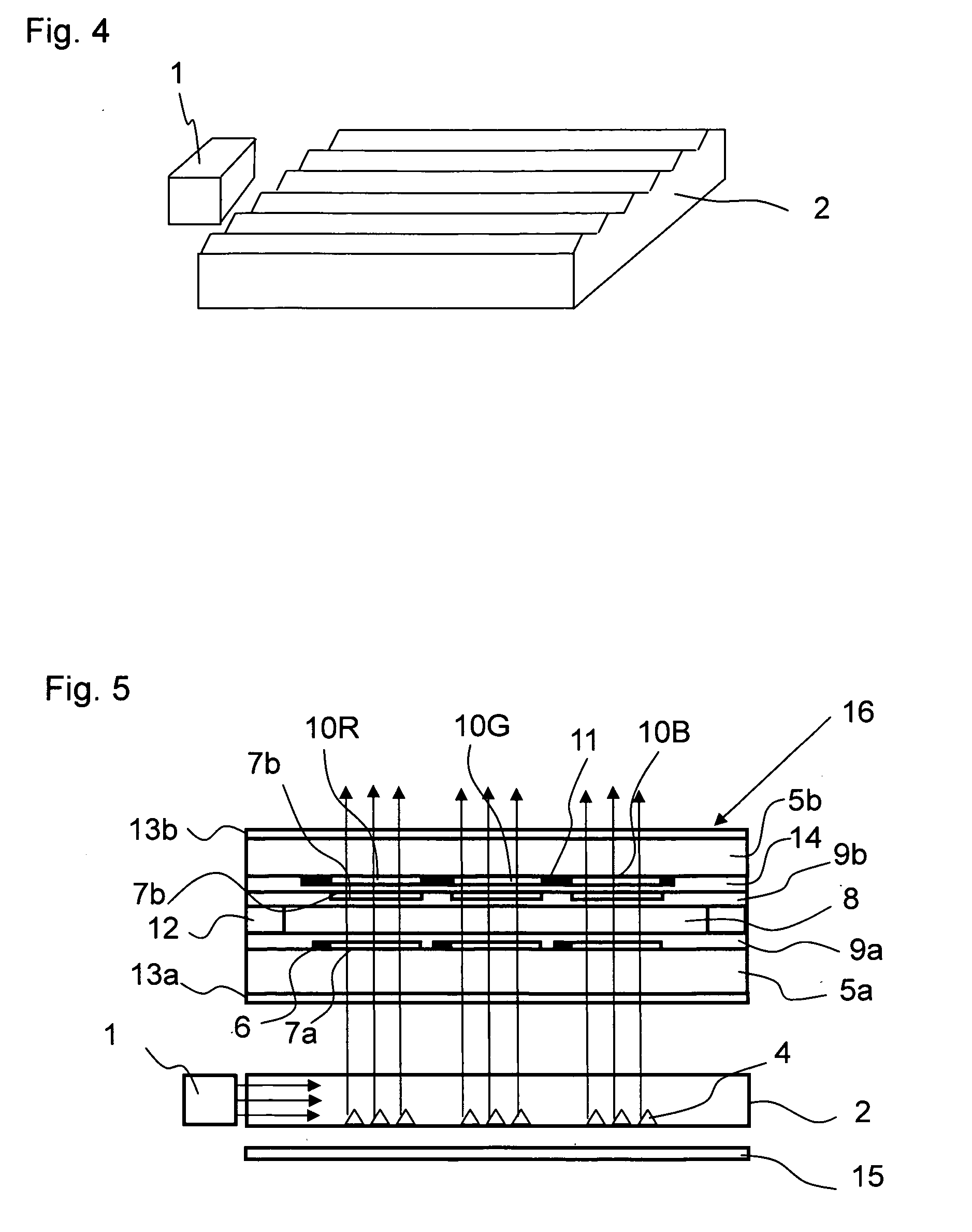
Figure 3
Abstract
Description
BACKGROUND OF THE INVENTION
[0001] 1. Field of the Invention
[0002] The present invention relates to a display device used in a portable information device such as a cellular phone or a mobile computer.
[0003] 2. Description of the Related Art
[0004] Conventionally, a liquid crystal display device that is small and thin and consumes less power is often used as a color image display device used in a portable information device such as a cellular phone or a mobile computer.
[0005] The liquid crystal display device includes a backlight as an illumination device. One known type of backlight is an edge-lit illumination device in which light from a light source enters on a side surface of a light guide plate and output from a top surface (hereinafter, referred to as exit surface) of the light guide plate. The light source includes a point light source such as a cathode ray tube or a light emitting diode (LED). The light guide plate has a surface (hereinafter, referred to as opposing surface) opposi...
Examples
example 1
[0026]A display device of Example 1 is described with reference to FIGS. 1 to 5.
[0027]FIG. 1 schematically illustrates a front structure of an illumination device of Example 1. In Example 1, a white light emitting diode (LED) package is used as a light source 1 of a backlight. The white LED package is of a type in which a blue LED is potted in a yellow fluorescent material. A light guide plate 2 is placed in front of the light source 1 and guides light emitted from the light source 1. In Example 1, the light source 1 is a point light source, and a white LED of a side view type is given as an example. However, the light source 1 may also be a white LED of a top view type or round lamp type, or an LED of a color other than white. The light guide plate 2 is a molded component formed of a transparent resin such as ZEONOR, polymethylmethacrylate (PMMA), or polycarbonate (PC). Light from the light source 1 propagates inside the transparent light guide plate 2, and is radiated to display e...
example 2
[0036]FIGS. 6a and 6b are front views each schematically illustrating a light guide plate 2 of Example 2. The light guide plates 2 of Example 2 are different from the light guide plate 2 of Example 1 in the shape of the entrance portion of the light guide plate 2. A semicircular depressed portion is provided to the incident surface of the light guide plate 2 to correspond to the light source 1, and functions as the entrance portion. When the entrance portion is a semicircular depressed portion as in Example 2, the light from the light source 1 is refracted by the semicircular entrance portion and then enters the light guide plate 2. Therefore, the light path is different from that of Example 1. Accordingly, optimum arrangement of the microprisms 4 is different from that of Example 1.
[0037]The entrance portion of FIG. 6a has a shape of a semicircle with a sharp tip, and the entrance portion of FIG. 6b has a shape of a semicircle with a blunt tip. A light path 3a and a light path 3b a...
example 3
[0038]FIG. 7 is a front view schematically illustrating a light guide plate 2 of Example 3. The light guide plate 2 of Example 3 is different from the light guide plates 2 of Examples 1 and 2 in the number of light sources 1 and an arrangement method of the microprisms 4. In Example 3, alight source 1c and a light source 1d are provided with respect to the incident surface of the light guide plate 2. Microprisms 4c and microprisms 4d are arranged on the light guide plate 2. The microprisms 4c and the microprisms 4d respectively correspond to the light source 1c and the light source 1d. The microprisms 4c and the microprisms 4d are alternately arranged. Each of the microprisms 4c is arranged so that a base of a mirror surface thereof is at about 90 degrees with respect to a light path 3c connecting the light source 1c and each of the microprisms 4c. Similarly, each of the microprisms 4d is arranged so that a base of a mirror surface thereof is at about 90 degrees with respect to a li...