
Apparatus for separating parts
a technology for separating parts and apparatuses, applied in the direction of absorbent pads, conveyers, articles, etc., to achieve the effect of simple and reliable apparatus design and compact structur
Patent Information
- Authority / Receiving Office
- US · United States
- Patent Type
- Applications(United States)
- Current Assignee / Owner
- Publication Date
- 2010-06-24
- Estimated Expiration
- Not applicable · inactive patent
Smart Images
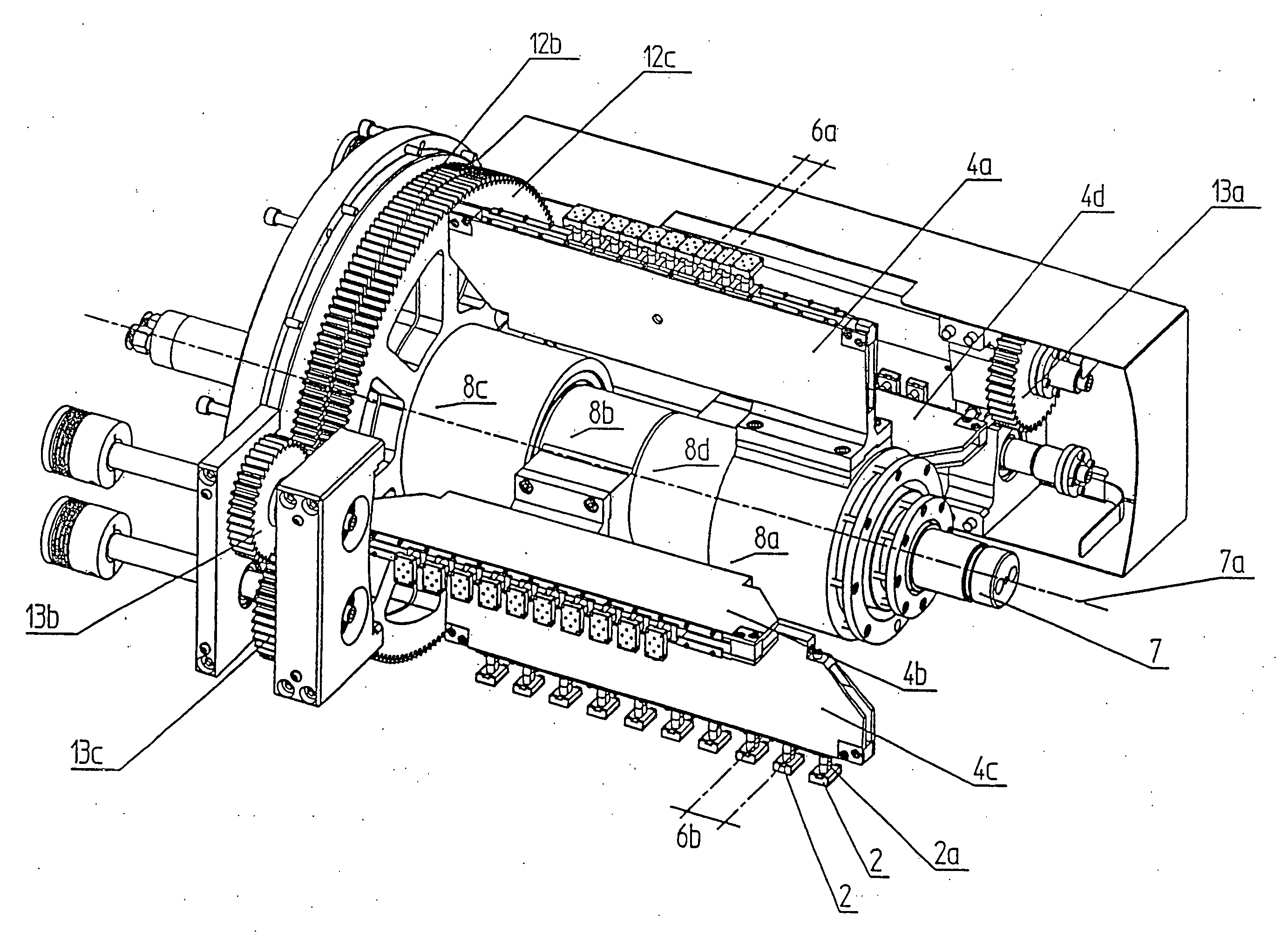
Figure 1 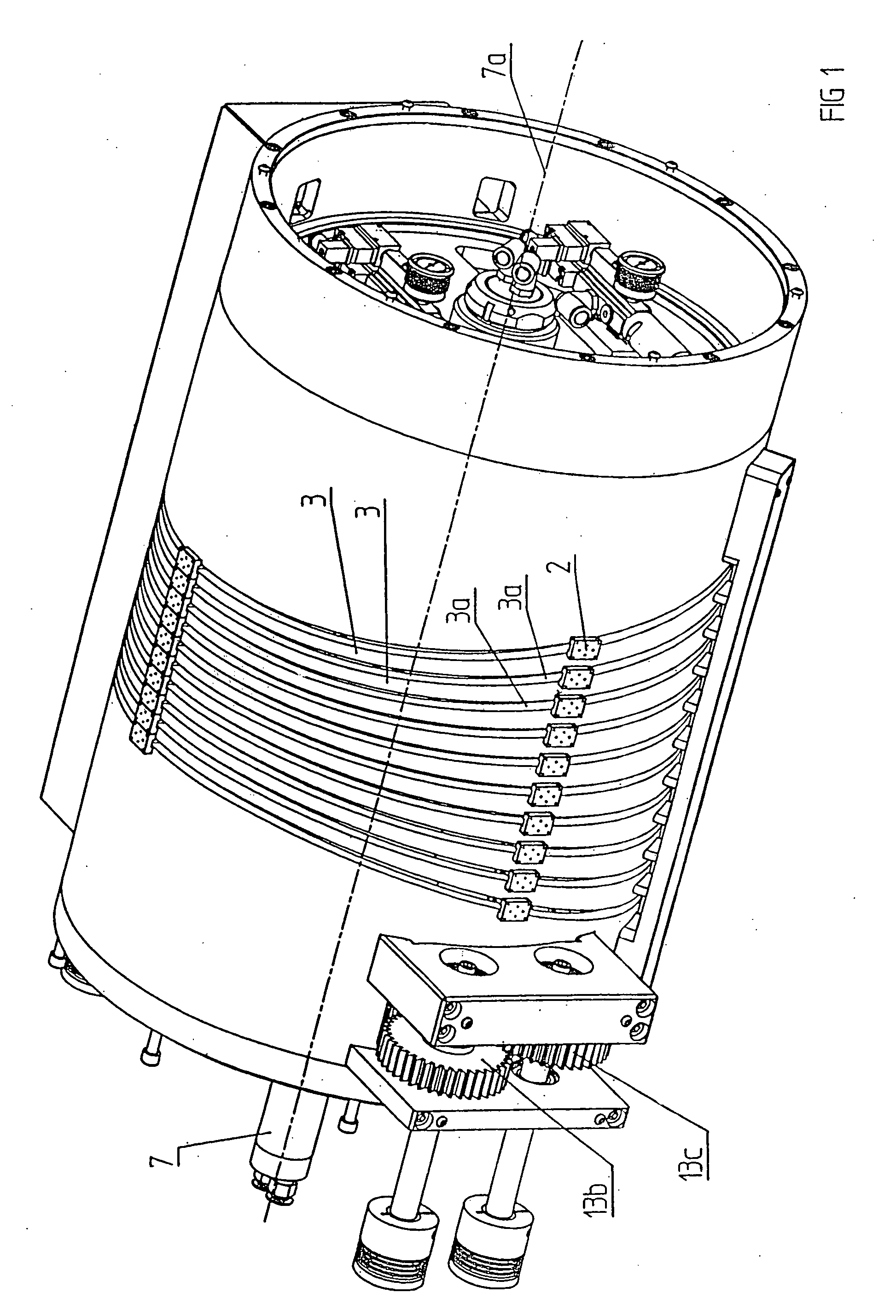
Figure 2 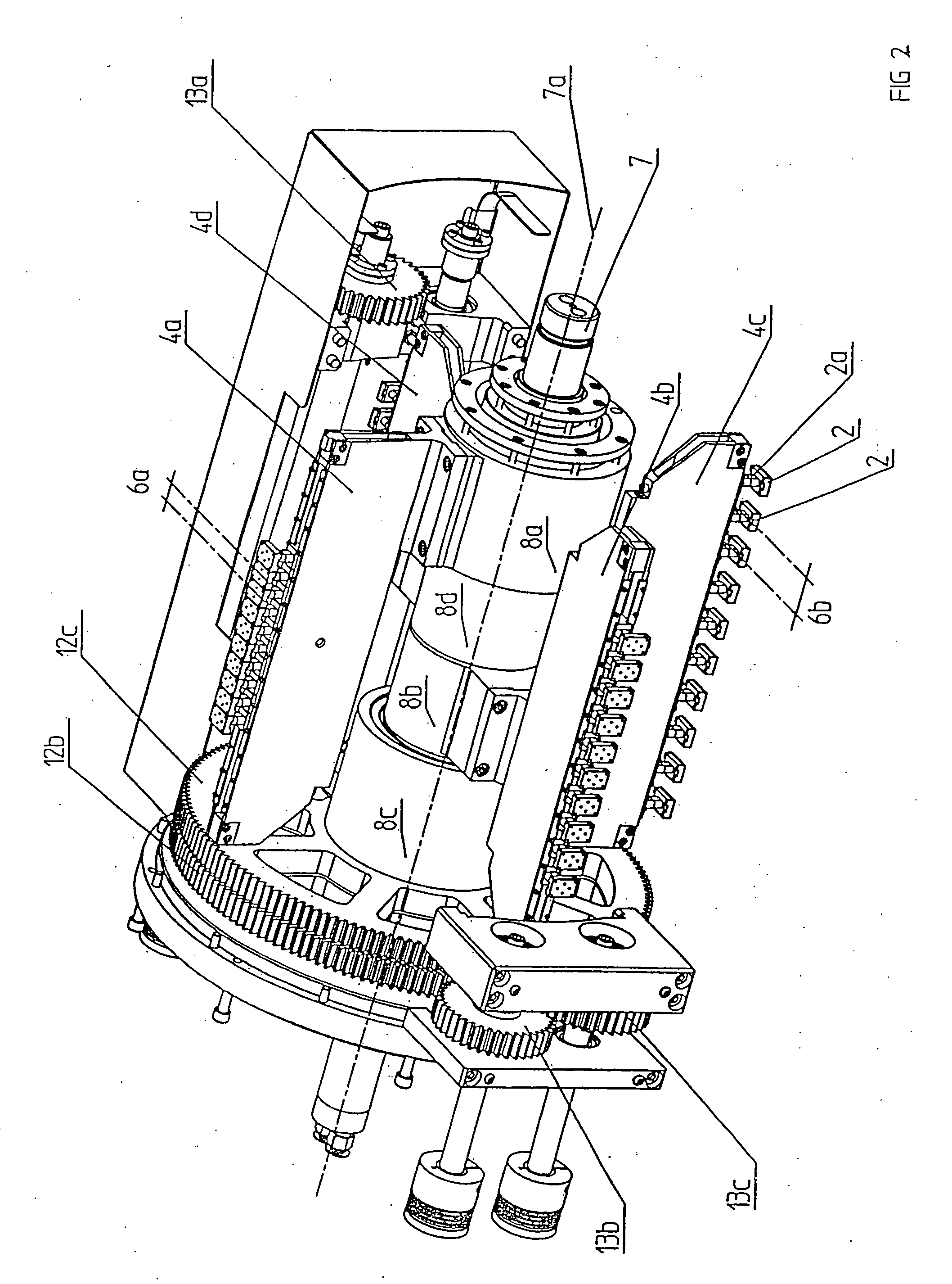
Figure 3
Abstract
Description
BACKGROUND OF THE INVENTION
[0001] The invention resides in an apparatus according to the preamble of claim 1 for separating for example parts arranged in at least two adjacent rows, including a transfer element having at least two retaining elements arranged side-by-side which engage parts in a first position and then deposit them in a second position.
[0002] Such apparatus are well-known in the art. They generally include an element which is rotatable about an axis and which is provided with several radially extending arms which are arranged side-by-side at a uniform angular distance from one another and which are provided at their ends with vacuum suction means. With the known apparatus, for example parts disposed on adjacently arranged transport belts can be grasped; pivoted by 90° or 180° and transferred to a downstream machine element.
[0003] The arms of the known separating apparatus are arranged firmly on a rotatable element in side-by-side relationship so that the distance at whi...
Examples
Embodiment Construction
[0023]As apparent in particular from FIGS. 1 to 3, a separating apparatus according to the invention includes holding elements in the form of vacuum suction devices 2 wherein in the present case ten vacuum suction devices 2 are arranged next to one another. The vacuum suction devices 2 are arranged on carriages which are movably supported in a groove of a transverse guide track 4a to 4d and are in communication with the vacuum suction devices 2 via neck portions 2a. With the movable support of the vacuum suction devices 2 by the transverse guide tracks 4a to 4d, the lateral distance 6a, 6b at which the vacuum suction devices 2 are arranged next to one another, that is the distance 6a, 6b between the center lines of the vacuum suction devices 2, can be changed.
[0024]The transverse guide tracks 4a to 4d are each mounted to a hollow shaft 8a-8d, which is disposed on a drive shaft 7 that is rotatable about an imaginary axis 7a. The vacuum suction devices 2 are therefore movable along a ...