
Shift control of continuously variable transmission
a technology of transmission and shift control, which is applied in the direction of road transport, instruments, gearing, etc., can solve the problems of shifting shock, inability to coordinate the upshift in the subtransmission mechanism, and inability to control the rotation speed of the internal combustion engine, so as to reduce the rotation variation and increase the amount of fuel consumed.
Patent Information
- Authority / Receiving Office
- US · United States
- Patent Type
- Applications(United States)
- Current Assignee / Owner
- Publication Date
- 2011-01-20
Smart Images
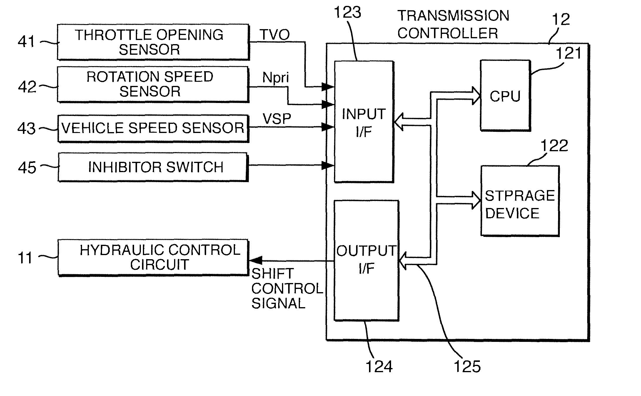
Figure 1 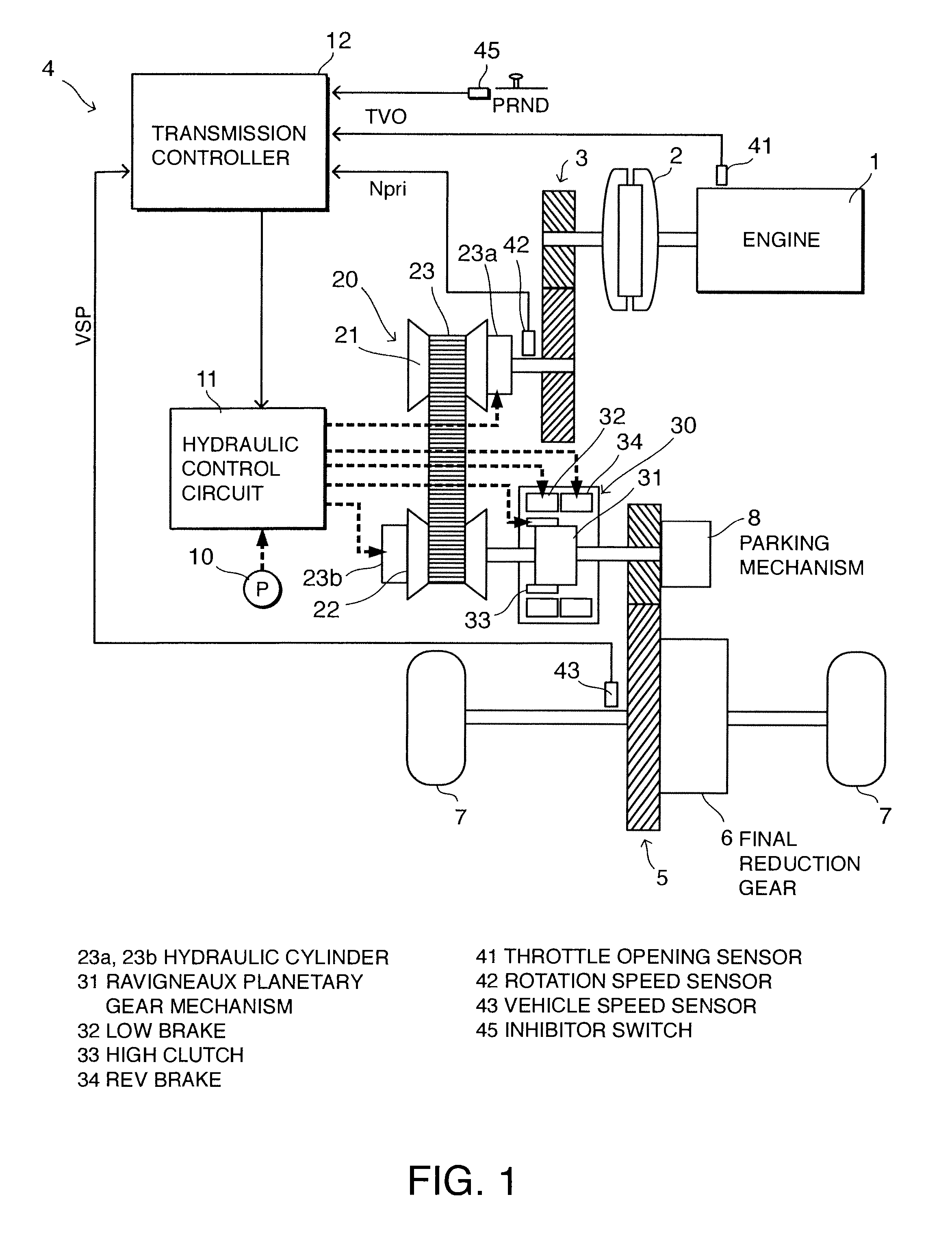
Figure 2 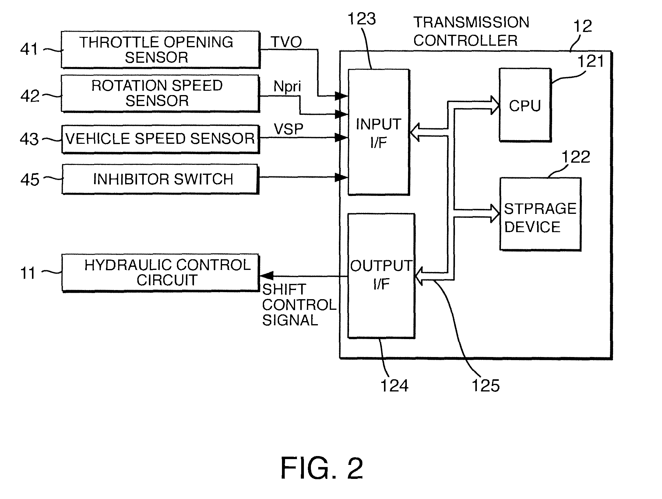
Figure 3
Abstract
Description
FIELD OF THE INVENTION
[0001] This invention relates to shift control performed on a continuously variable transmission comprising a continuously variable transmission mechanism and a subtransmission mechanism.BACKGROUND OF THE INVENTION
[0002] A continuously variable transmission is a transmission which is capable of varying a speed ratio continuously.
[0003] In a vehicle installed with a continuously variable transmission, an internal combustion engine can be operated more efficiently than in a vehicle having a conventional stepped transmission, and therefore improvements in a power performance and a fuel performance of the vehicle can be expected.
[0004] To improve the power performance and fuel efficiency performance of a vehicle installed with a continuously variable transmission even further, a possible speed ratio range (to be referred to hereafter as a “ratio range”) of the continuously variable transmission is preferably enlarged.
[0005] When the ratio range of the continuously varia...
Examples
second embodiment
[0120]Next, referring to FIG. 10, this invention will be described.
first embodiment
[0121]The hardware constitution of this embodiment is identical to that of the The shift controller 12 according to this embodiment performs upshift control on the subtransmission mechanism 30 using a shift map having the characteristics shown in FIG. 10 instead of the shift map having the characteristics shown in FIG. 5.
[0122]In the first embodiment, the shift controller 12 switches between the normal upshift determining line and the low load / high speed region upshift determining line, as shown in FIG. 5, whereas in this embodiment, the subtransmission mechanism 30 is upshifted using a single upshift determining line.
[0123]The minimum vehicle speed for an upshift on the single upshift determining line is set similarly to the minimum vehicle speed for an upshift on the low load / high speed region upshift determining line of the first embodiment. In the region where the primary rotation speed Npri is equal to or greater than the lowest rotation speed, the normal upshift determining l...