
Control device for direct fuel injection engine and control method thereof
a technology of control device and direct fuel injection engine, which is applied in the direction of electric control, fuel injection control, machines/engines, etc., can solve the problems of lowering heat efficiency, fuel efficiency deterioration, and heat efficiency, so as to reduce heat efficiency, reduce compression ratio, and suppress knocking
Patent Information
- Authority / Receiving Office
- US · United States
- Patent Type
- Applications(United States)
- Current Assignee / Owner
- Publication Date
- 2020-07-02
Smart Images
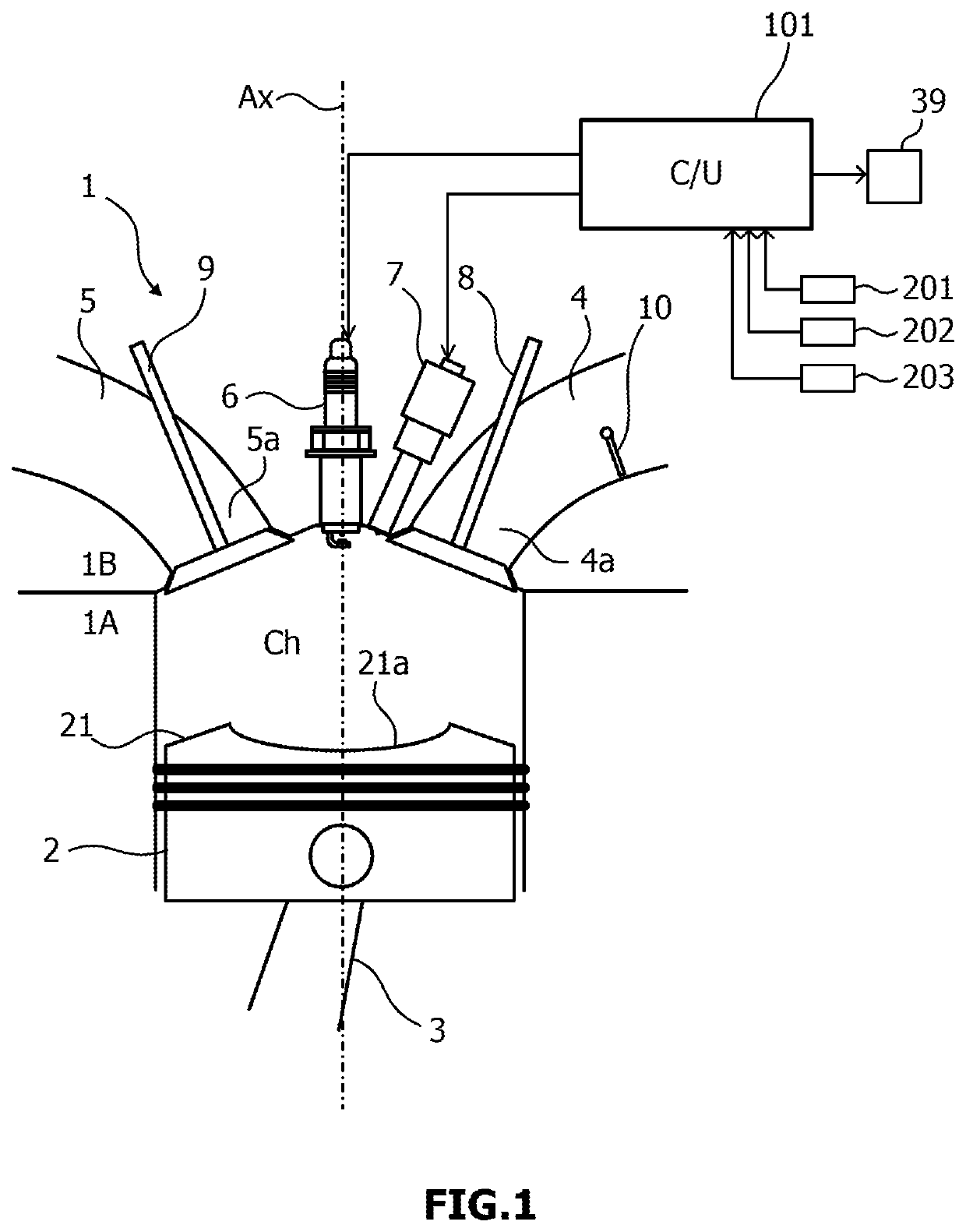
Figure 1 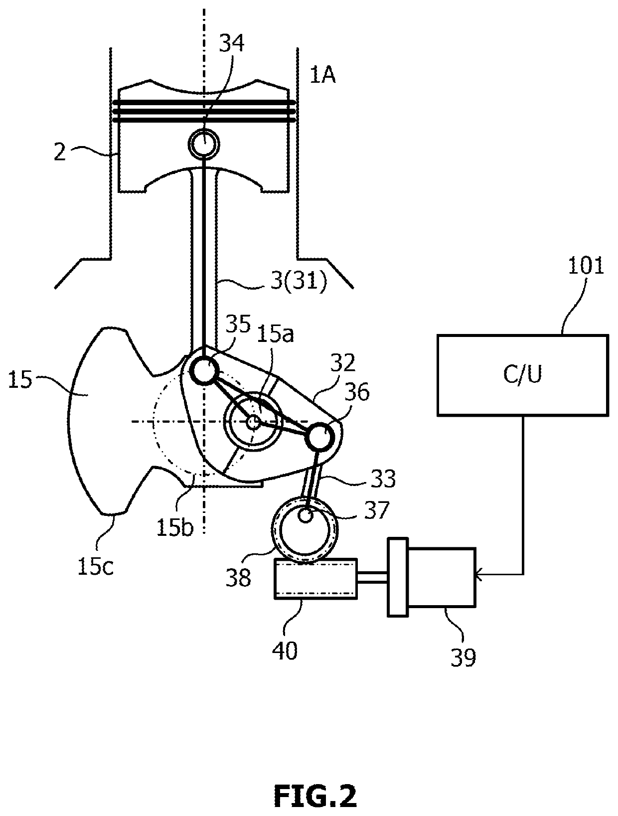
Figure 2 
Figure 3
Abstract
Description
TECHNICAL FIELD
[0001] The present invention relates to a direct fuel injection engine operated by a lean air-fuel mixture with an excess air ratio in the vicinity of 2 and a control method thereof.BACKGROUND ART
[0002] A demand for improvement of fuel efficiency of an internal combustion engine has increased for further reduction of an environmental load. Leaning of the air-fuel mixture is an already known measure for improving the fuel efficiency of the internal combustion engine. However, even under combustion by the lean air-fuel mixture, in an operation region where an engine load is high and a fuel supply amount is large, knocking occurs in some cases. As an art for suppressing the knocking, retarding of ignition timing is known.
[0003] JP2010-116876 discloses retarding of the ignition timing in order to suppress the knocking in a high load region. Specifically, whether it is in a high load region having a high heat load is determined on the basis of an engine load, a revolution spe...
Examples
Embodiment Construction
[0019]An embodiment of the present invention will be described below by referring to the attached drawings.
[0020](Entire Configuration of Engine)
[0021]FIG. 1 is a configuration diagram of a direct fuel injection engine (spark ignition engine and hereinafter, referred to as an “engine”) 1 according to an embodiment of the present invention.
[0022]The engine 1 has its body formed by a cylinder block 1A and a cylinder head 1B, and a cylinder or an air cylinder is formed as a space surrounded by the cinder block 1A and the cylinder head 1B. FIG. 1 illustrates only one cylinder, but the engine 1 may be a multi-cylinder type direct fuel injection engine having a plurality of cylinders.
[0023]A piston 2 is inserted into the cylinder block 1A capable of reciprocating up / down along a cylinder center axis Ax, and the piston 2 is connected to a crank shaft, not shown, through a connecting rod 3. A reciprocating motion of the piston 2 is transmitted to the crank shaft through the connecting rod 3...