
Automotive vehicle brake system
a brake system and automobility technology, applied in the direction of braking components, position/direction control, special data processing applications, etc., can solve the problems of reducing fuel efficiency, increasing emissions, and kinetic energy collected during regenerative braking, and achieves smooth and consistent regenerative deceleration and boosted feel
Patent Information
- Authority / Receiving Office
- US · United States
- Current Assignee / Owner
- Publication Date
- 2012-06-07
- Estimated Expiration
- Not applicable · inactive patent
Smart Images
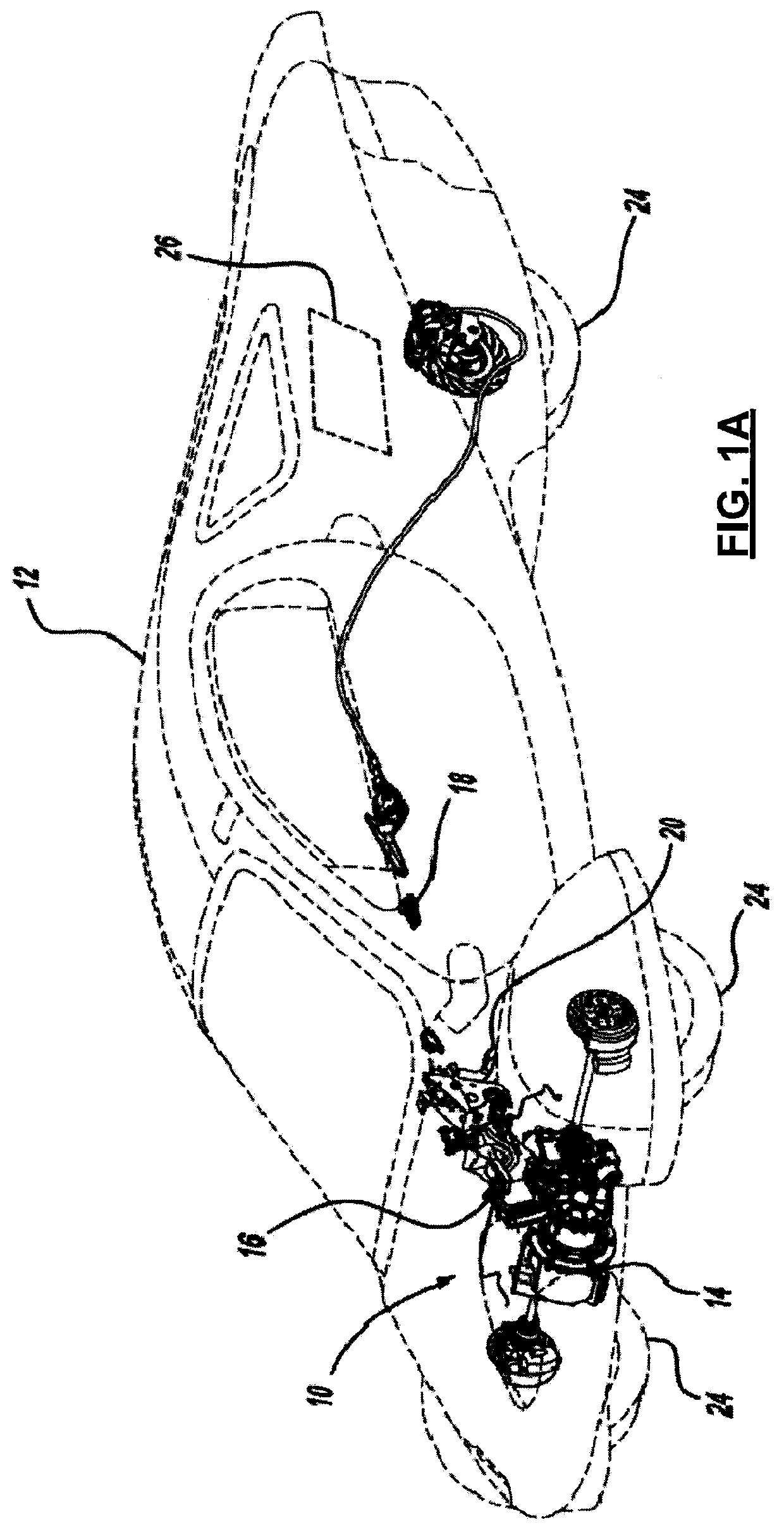
Figure 1 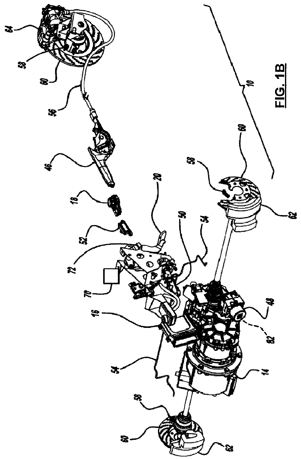
Figure 2 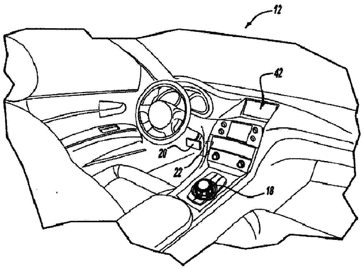
Figure 3
Abstract
Description
BACKGROUND AND SUMMARY
[0001] The present invention generally pertains to an automotive vehicle brake system and more particularly to a regenerative brake system.
[0002] A conventional braking system typically utilizes friction between brake pads and brake rotors for slowing or stopping a vehicle. This action dissipates the vehicle's kinetic energy as heat energy. This friction and resulting dissipation of kinetic energy wastes the vehicle's generated power, reduces fuel efficiency, and leads to higher emissions. It is possible, however, to counter this waste by converting the vehicle's kinetic energy into a form that can later be reused. For example, the vehicle's kinetic energy may be captured and stored for use in a process known as regenerative braking. The kinetic energy collected during regenerative braking, however, does not restore all energy lost during vehicle operation. Moreover, a brake pedal may behave and “feel” differently in regenerative braking systems, as opposed to co...
Examples
Embodiment Construction
[0020]The preferred embodiment of a regenerative braking system 10 for an electric drive vehicle 12 is illustrated and described with respect to FIGS. 1 through 12. System 10, as described herein, allows kinetic energy from vehicle 12 to be re-absorbed by an energy storage system, achieves a consistent braking system meeting Federal Motor Vehicle Safety Standards (FMVSS), and meets specific performance objectives (e.g., stopping distance, pedal force application, relationships between brake pedal force, displacement, and vehicle deceleration, etc.), while smoothly blending the transition between electrical regenerative braking and friction braking.
[0021]With reference now to FIGS. 1 through 4, vehicle 12 includes regenerative braking system 10, an electric motor 14 with an inverter 15, a vehicle control unit or module (VCU) 16, an electronic shift controller 18, a brake pedal 20, and an accelerator pedal 22. During vehicle acceleration, electric motor 14 converts electrical energy i...