
Optical lens, lens unit, imaging module, and electronic apparatus
a technology of optical lenses and imaging modules, applied in the field of optical lenses, lens units, imaging modules, electronic devices, can solve the problem that the influence of light reflection at the surface of light blocking layers on the quality of captured images cannot be ignored
Patent Information
- Authority / Receiving Office
- US · United States
- Patent Type
- Applications(United States)
- Current Assignee / Owner
- Publication Date
- 2015-04-16
- Estimated Expiration
- Not applicable · inactive patent
Smart Images
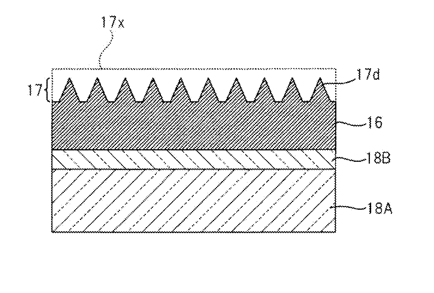
Figure 1 
Figure 2 
Figure 3
Abstract
Description
CROSS-REFERENCE TO RELATED APPLICATIONS
[0001] This application is based on and claims priority under 35 USC 119 from Japanese Patent Application No. 2013-214730 filed on Oct. 15, 2013, and Japanese Patent Application No. 2014-040560 filed on Mar. 3, 2014, the entire contents of which are incorporated herein by reference.BACKGROUND
[0002] 1. Technical Field
[0003] The present invention relates to an electronic apparatus such as a digital camera Or a mobile phone, an imaging module which is incorporated and used in the electronic apparatus, and an optical lens and a lens unit mounted in the imaging module.
[0004] 2. Related Art
[0005] In an imaging module which is incorporated and used in an electronic, apparatus such as a digital camera or a mobile phone, improvement has progressed in order to prevent the occurrence of flare or ghosting by removing torr incident light, thereby allowing the quality of a captured image to be improved. As an image quality countermeasure, for example, a configura...
Examples
example 1
[0098]An AR coat was applied on a lens base material body made of the material a so that a lens base material was formed, and then the material A was coated on part of a surface of the lens base material by an ink jetting method. Then, a mold having a moth-eye irregular structure was brought into pressing contact with the coated film of the material A, and the coated film was cured in this state so that an antireflection layer and a light blocking layer were formed. A part where irregularities were formed in the cured coated film is divided into ten parts in a direction perpendicular to the surface of the lens base material, and a refractive index of each divided layer was measured and results are shown in Table 3. In Table 3, a smaller layer number indicates that a corresponding layer is closer to an air layer.
TABLE 3LayerSpatial Occupation Ratio [%]Effective Refractive Index10.8261.00423.3061.01537.4381.033413.2231.059520.6611.093629.7571.135740.4961.186852.8931.246966.9421.317108...
example 2
[0099]An AR coat was applied on a lens base material body made of the material b so that a lens base material was formed, and then the material B was coated on part of a surface of the lens base material by an ink jetting method and was then dried and cured so that a light blocking layer was formed. Then, an aqueous solution containing zinc nitrate and ethylenediamine was coated and dried on the light blocking layer with a sodium hydroxide aqueous solution as a solvent so that zinc oxide was deposited, thereby allowing an antireflection layer with a moth-eye structure to be formed. The antireflection layer has a refractive index which is slightly higher than 1 on the air layer and a refractive index of 1.65 on the light blocking layer side.
example 3
[0100]Au antireflection layer with a moth-eye structure, made of Al2O3 was formed on the light blocking layer of the optical lens which was manufactured in Comparative Example 1. The antireflection layer has a refractive index which is slightly higher than 1 on the an layer side and a refractive index of 1.4 on the light blocking layer side.