
Liquid-cooled turbine housing with intermediate chamber
a technology of turbine housing and intermediate chamber, which is applied in the direction of combustion engines, machines/engines, engine fuction, etc., can solve the problems of affecting the internal walls of the exducer region of the turbine housing will interfere, and the problem of quickly escalating into a broken turbine wheel blade, etc., to achieve the effect of improving the efficiency of the turbine stage, reducing thermal strain, and not losing thermal efficiency
Patent Information
- Authority / Receiving Office
- US · United States
- Patent Type
- Applications(United States)
- Current Assignee / Owner
- Publication Date
- 2016-10-06
- Estimated Expiration
- Not applicable · inactive patent
Smart Images
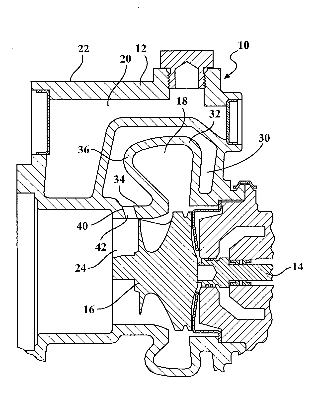
Figure 1 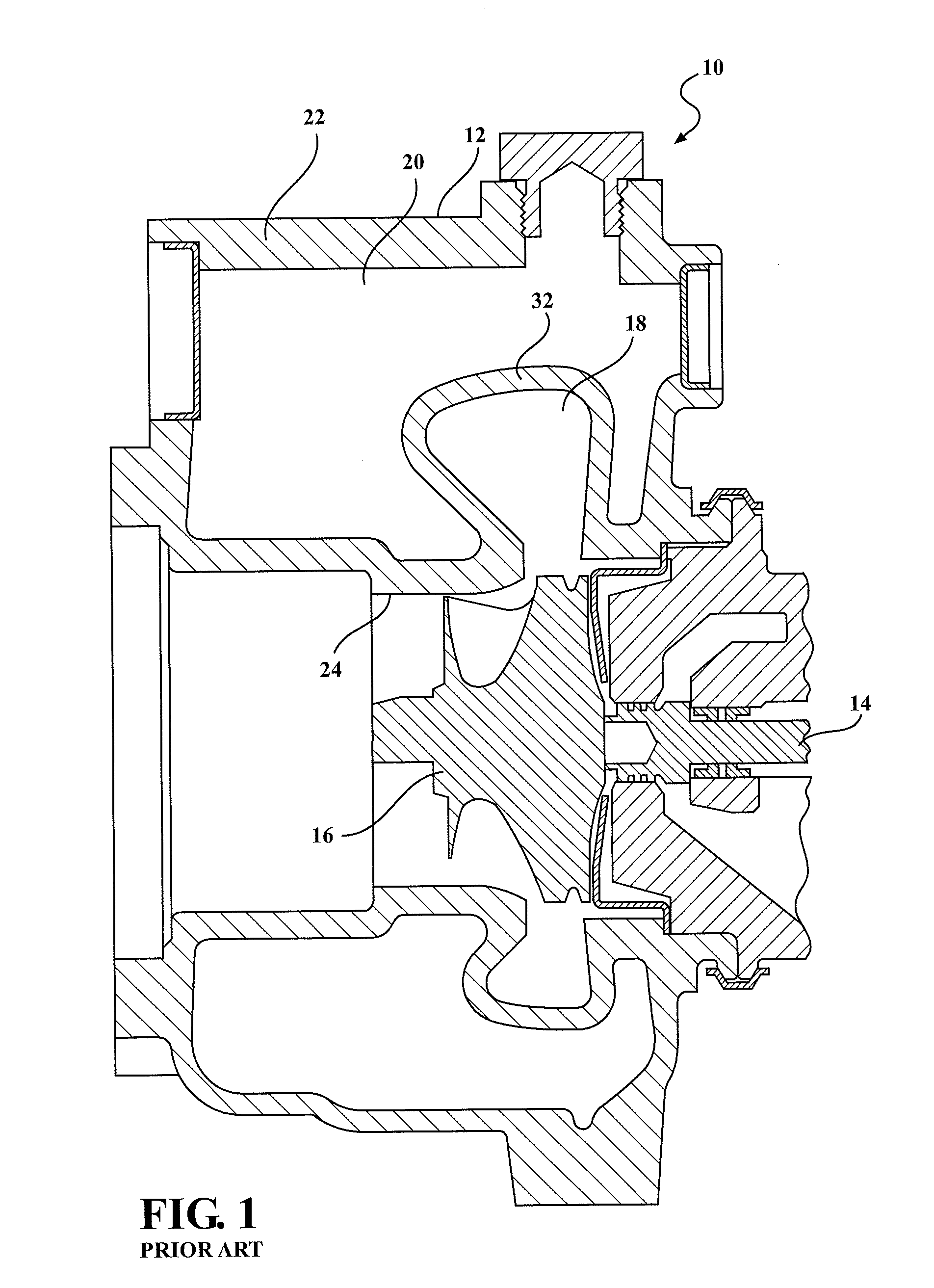
Figure 2 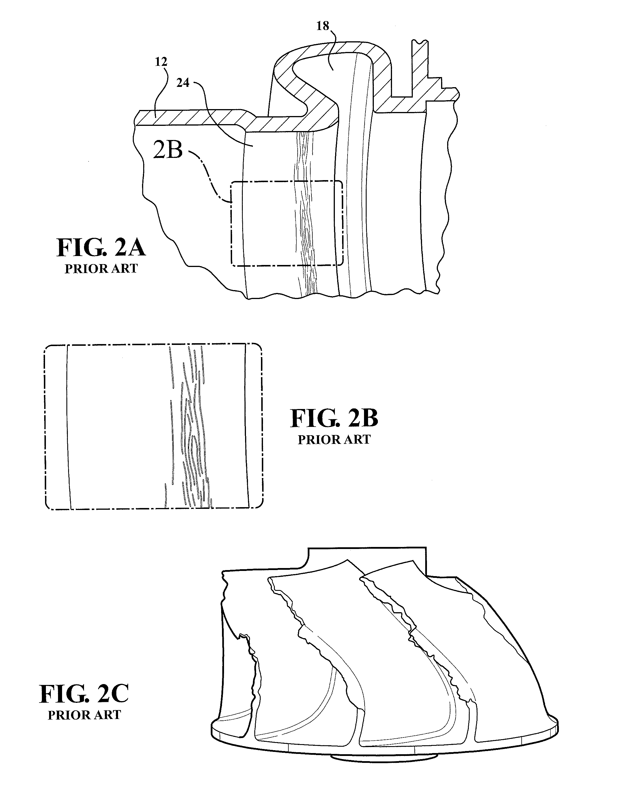
Figure 3
Abstract
Description
CROSS-REFERENCE TO RELATED APPLICATION
[0001] This application claims priority to and all the benefits of U.S. Provisional Application No. 61 / 903,431, filed on Nov. 13, 2013, and entitled “Liquid-Cooled Turbine Housing with Intermediate Chamber,” which is incorporated herein by reference.BACKGROUND
[0002] 1. Field of the Disclosure
[0003] This disclosure relates to liquid-cooled turbine housings for turbochargers. More particularly, this disclosure relates to an intermediate chamber adjacent to a liquid cooling chamber of the turbine housing.
[0004] 2. Description of Related Art
[0005] Advantages of turbocharging include increased power output, lower fuel consumption, reduced pollutant emissions, and improved transient response. The turbocharging of engines is no longer primarily seen from a high-power performance perspective, but is rather viewed as a means of reducing fuel consumption and environmental pollution on account of lower carbon dioxide (CO2) emissions. Currently, a primary reason...
Examples
Embodiment Construction
[0024]Referring to FIG. 3, a turbocharger 10 includes a compressor wheel (not shown) in a compressor housing (not shown) that is rotatably driven via a rotatable shaft 14 by a turbine wheel 16 in a turbine housing 12. The turbine housing 12 is a liquid-cooled turbine housing 12, and includes an exhaust gas inlet (not shown) configured to be connected to an exhaust manifold of an engine. The turbine housing 12 includes an exhaust gas outlet (e.g., an exducer) 24, and a volute 18. The volute 18 defines a main chamber that surrounds the turbine wheel 16, and directs hot exhaust gas toward blades of the turbine wheel 16. The turbine housing 12 further includes an outer shell 22. A liquid chamber 20, for example a water core, is defined between the outer shell 22 and an inner wall 36 that includes a wall portion 32 forming the volute 18 and a wall portion 34 forming the exducer 24. Thus, the liquid chamber 20 is adjacent to an outer shell 22 of the turbine housing 12.
[0025]The turbocharg...