
Light source and atomic oscillator
Patent Information
- Authority / Receiving Office
- US · United States
- Current Assignee / Owner
- Publication Date
- 2017-04-27
- Estimated Expiration
- Not applicable · inactive patent
Smart Images
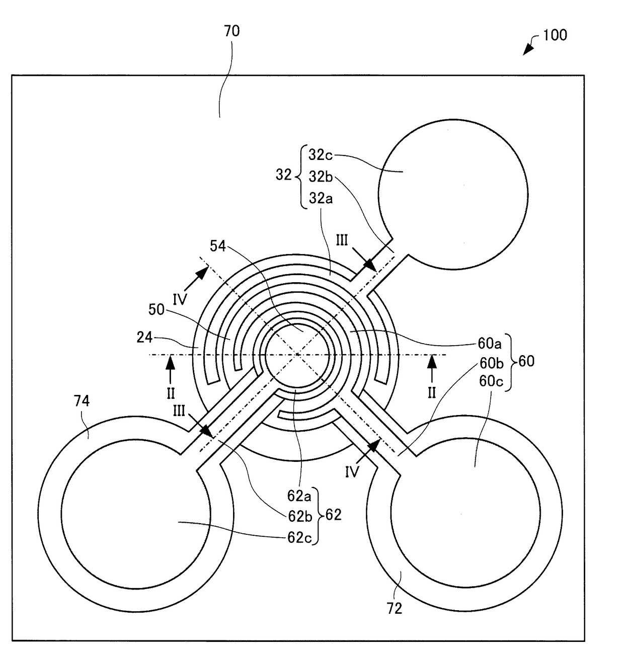
Figure 1 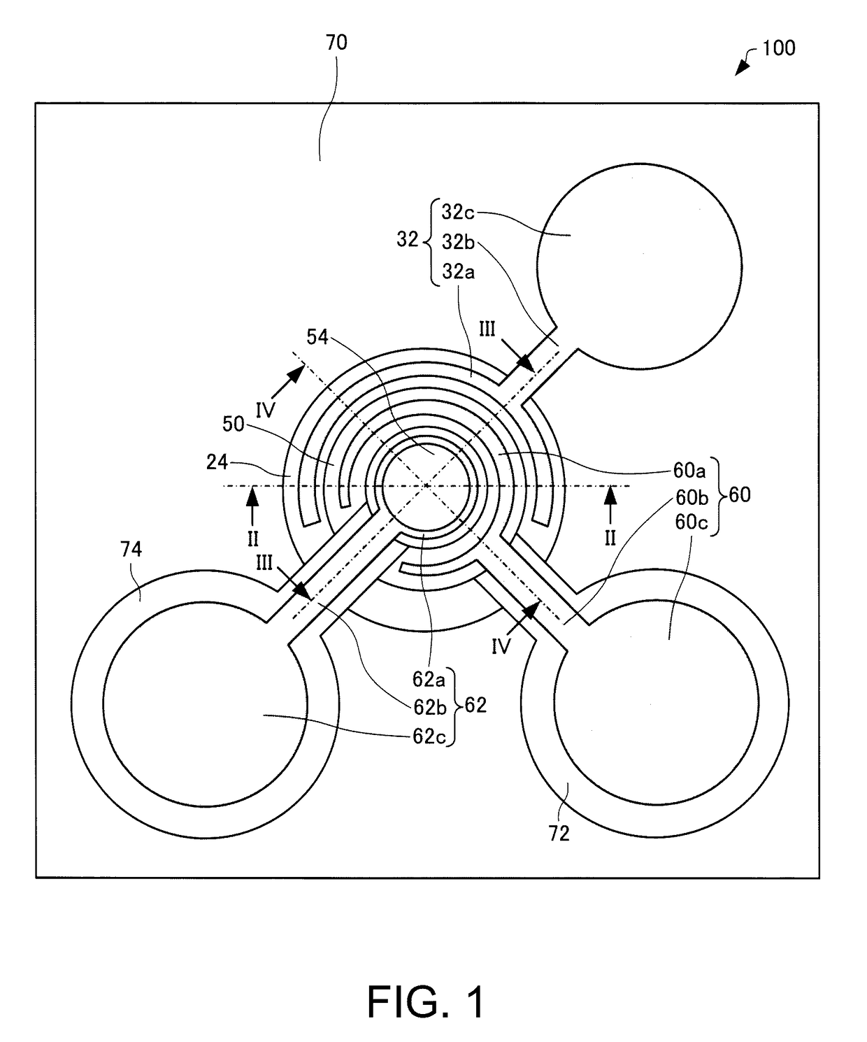
Figure 2 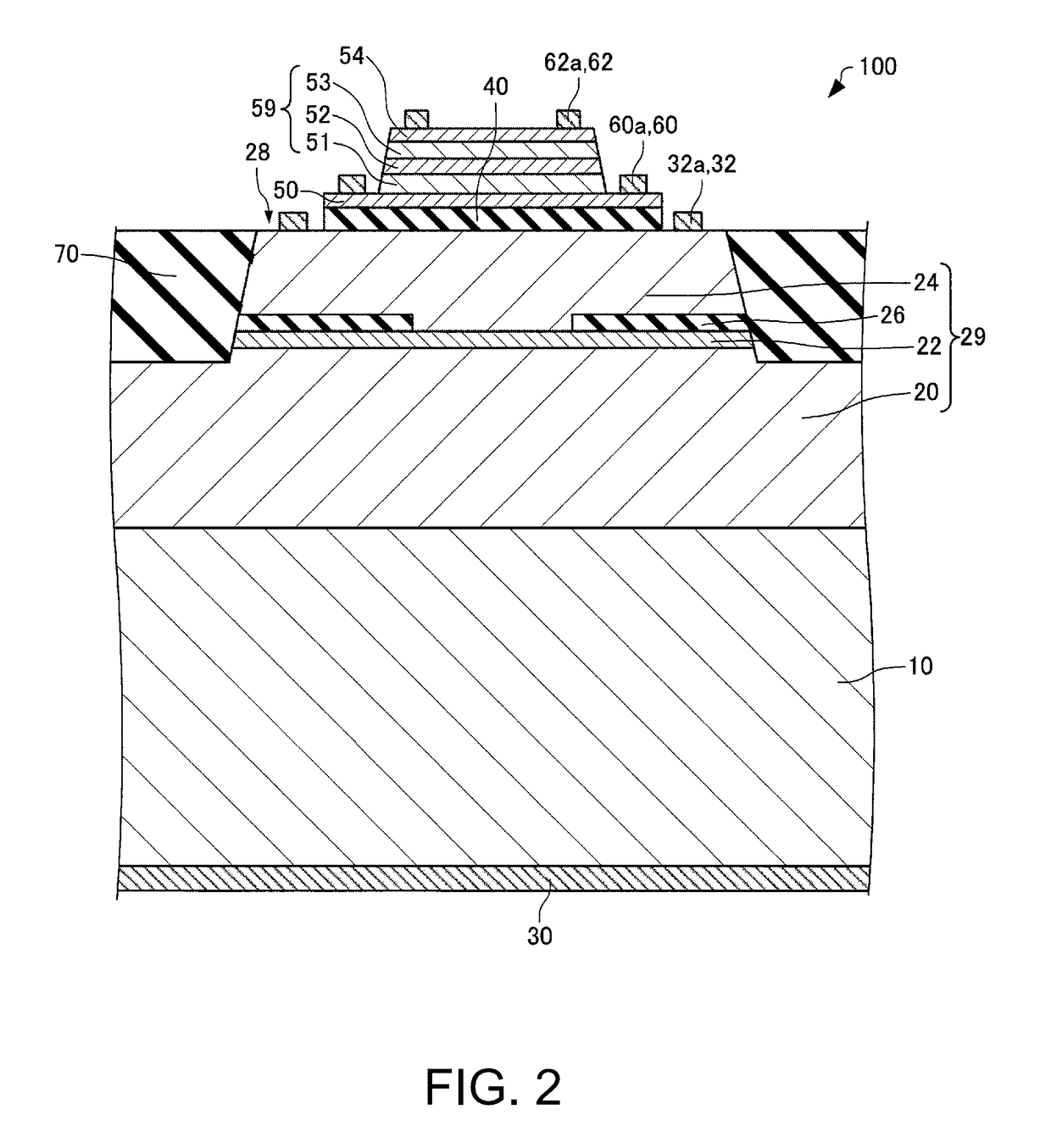
Figure 3
Abstract
Description
BACKGROUND
[0001] 1. Technical Field
[0002] The present invention relates to a light source and an atomic oscillator.
[0003] 2. Related Art
[0004] An atomic oscillators using transition energy of atoms as reference frequency is widely used as one of highest-precision oscillators in communication base stations or the like. Although there are several types as the atomic oscillator, a microwave double resonance type using a rubidium (Rb) lamp is most generally used.
[0005] In recent years, an atomic oscillator using a phenomenon called Coherent Population Trapping (CPT) that is one of quantum interference effects is suggested (for example, refer to JP-A-2015-62167), and reduced size and low power consumption of the atomic oscillator are expected compared with the related art. In the case of the CPT type, sidebands are used for development of a CPT phenomenon by superimposing a high-frequency signal using a coherent light source, such as a laser, as a light source. The CPT type atomic oscillator ...
Examples
first modification example
3.1. First Modification Example
[0081]Next, a light source according to the first modification example of the present embodiment will be described, referring to drawings. FIG. 9 is a sectional view schematically illustrating a light source 200 according to the first modification example of the present embodiment. FIG. 10 is a plan view schematically illustrating the light source 200 according to the first modification example of the present embodiment. It should be noted that illustration of members other than the contacting part 62a of the fourth electrode 62, the first contact layer 50, and the heat insulating layer 40, is omitted in FIG. 10 for convenience.
[0082]Hereinafter, in the light source 200 according to the first modification example of the present embodiment, members having the same functions as those of the constituent members of the light source 100 according to the present embodiment will be designated by the same reference signs, and the detailed description thereof w...
second modification example
3.2. Second Modification Example
[0089]Next, a light source according to a second modification example of the present embodiment will be described, referring to drawings. FIG. 12 is a plan view schematically illustrating a light source 300 according to the second modification example of the present embodiment. FIG. 13 is a sectional view, taken along line XIII-XIII of FIG. 12, schematically illustrating the light source 300 according to the second modification example of the present embodiment.
[0090]The light source 300, as illustrated in FIG. 13, is different from the above-described light source 100 in that the light source 300 has a heat diffusion layer 42.
[0091]The heat diffusion layer 42 is provided on the heat insulating layer 40. The heat diffusion layer 42 is provided between the heat insulating layer 40 and the first contact layer 50. A planar shape of the heat diffusion layer 42 is, for example, circular. In the plan view, the area of the heat diffusion layer 42 and the are...