
Steer-by-wire steering apparatus
a steering apparatus and wire technology, applied in the direction of vehicle sub-unit features, transportation and packaging, gearing, etc., can solve the problems of poor steering feel and indefinite rotation of the driver's steering wheel, and achieve the effect of better steering feel
Patent Information
- Authority / Receiving Office
- US · United States
- Patent Type
- Applications(United States)
- Current Assignee / Owner
- Publication Date
- 2022-05-12
Smart Images
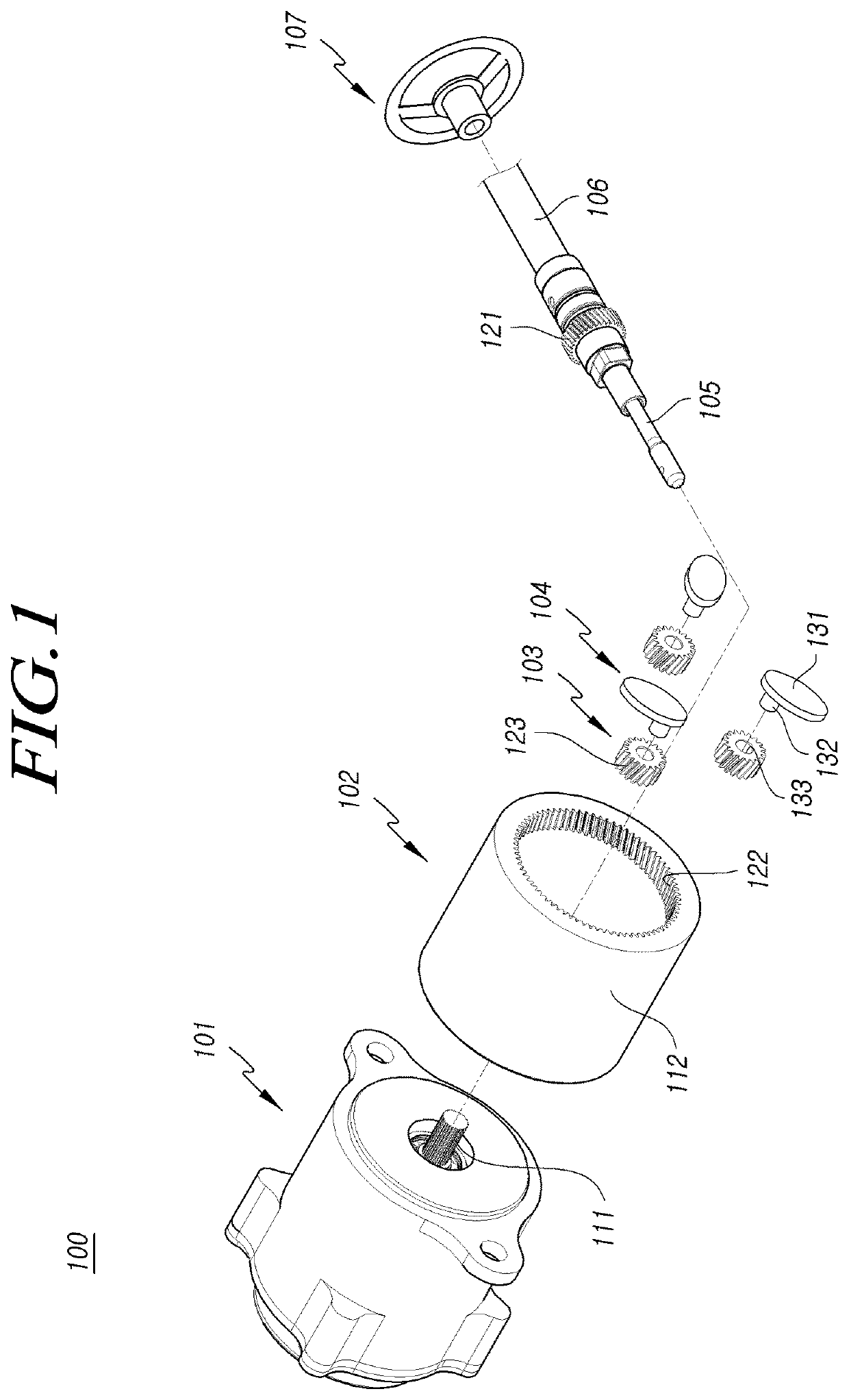
Figure 1 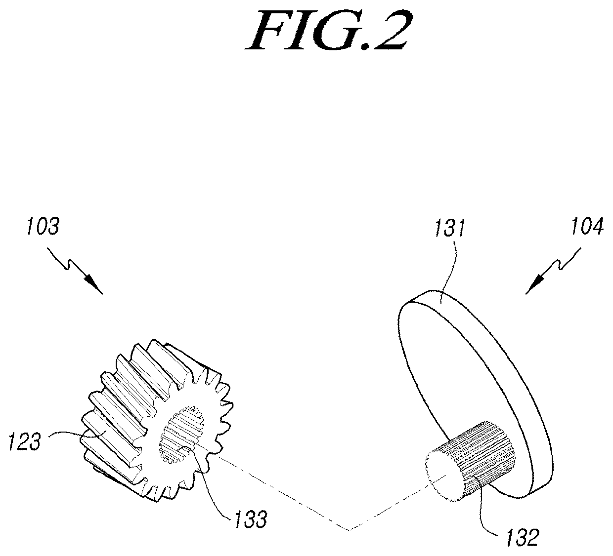
Figure 2 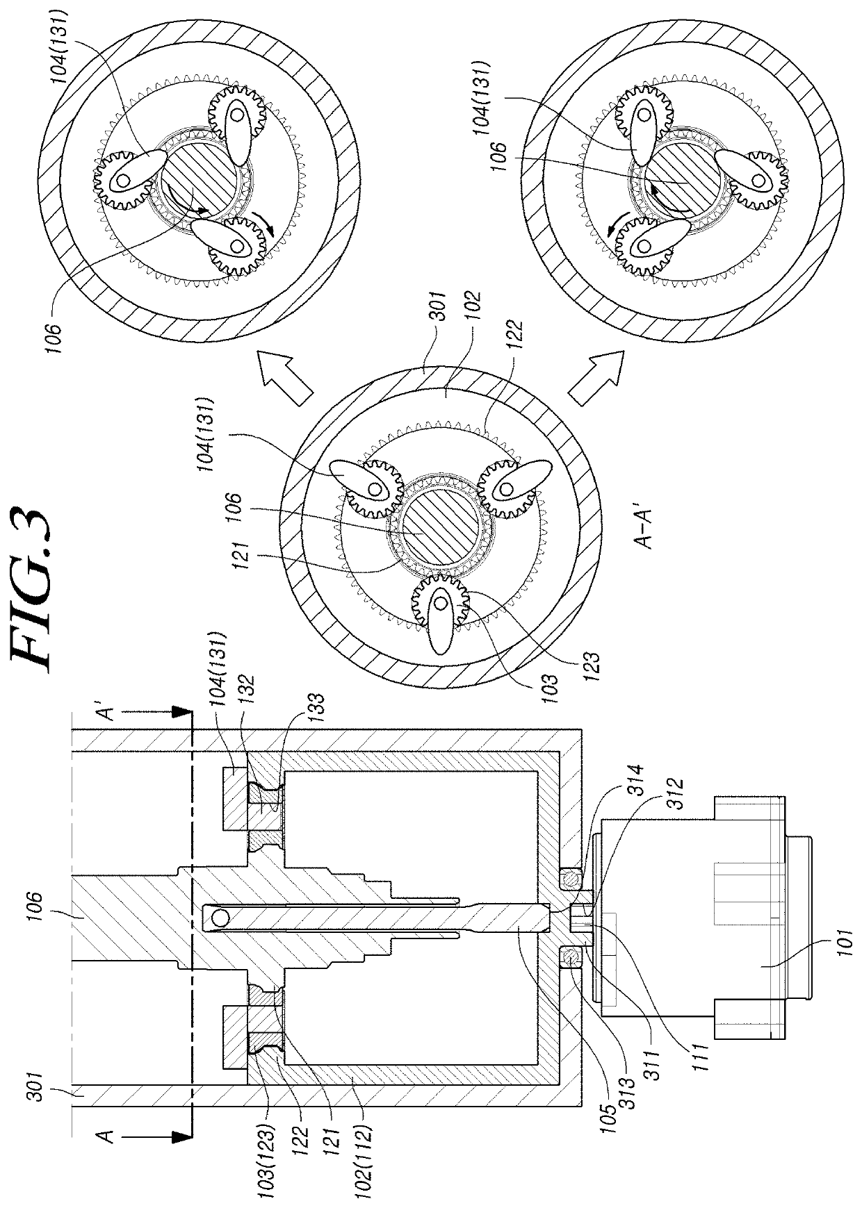
Figure 3
Abstract
Description
TECHNICAL FIELD
[0001] The present embodiments relate to a steer-by-wire steering device, and more particularly, to a steer-by-wire steering device that may provide a better steering feel by mechanically stopping the steering shaft from rotating when the driver applies a steering torque greater than the reaction torque of the reaction force motor to the steering shaft.BACKGROUND ART
[0002] A steer-by-wire steering device is a kind of electromotive steering device that steers the vehicle using electric power without any mechanical connection, such as a steering column or universal joint, between the steering wheel and the front wheel steering device.
[0003] In other words, the driver's manipulation of the steering wheel is converted into an electric signal, and the electronic control device receives the electric signal and accordingly determines the output of the motor. Due to a lack of mechanical connection, the steer-by-wire system reduces injury to the driver by a mechanical part when a...
Examples
first embodiment
[0048]Referring to a first embodiment illustrated in FIG. 3, the second gear part 122 is formed at one end of the receiving part 112, so that the stopper 104 is not stuck to the receiving part 112 or the housing 301 when the second rotor 103 rotates and, when the steering shaft 106 is rotated to one side or the opposite, the supporting part 131 is supported on the outer circumferential surface of the steering shaft 106 while restricting rotation of the second rotor 103.
[0049]As the supporting part 131 is supported on the outer circumferential surface of the steering shaft 106 and the range in which the second rotor 103 is rotatable is limited by the stopper 104, the rotation of the steering shaft 106 is prevented.
[0050]Or, as the supporting part 131 is supported on the outer circumferential surface of the steering shaft 106 or the inner circumferential surface of the housing 301, the rotation angle range of the second rotor 103 may be limited.
[0051]Referring to a second embodiment i...
third embodiment
[0056]Referring to a third embodiment illustrated in FIG. 5, a second stepped part 502 may be formed which faces the first stepped part 501 and radially protrudes from the inner circumferential surface of the housing 301 to allow the supporting part 131 to be supported on the inner circumferential surface of the housing 301 when the second rotor 103 rotates.
[0057]In other words, when the steering shaft 106 is rotated to one side or the opposite, the supporting part 131 may be supported by the second stepped part 502, restricting the rotation of the second rotor 103.
fourth embodiment
[0058]Referring to a fourth embodiment illustrated in FIG. 6, the receiving part 112 may have an extension 601 that extends to an axial side from where the second gear part 122 is formed, to allow the supporting part 131 to be supported on the inner circumferential surface of the receiving part 112 when the second rotor 103 rotates.
[0059]In other words, when the steering shaft 106 is rotated to one side or the opposite, the supporting part 131 may be supported on the inner circumferential surface of the extension 601, restricting rotation of the second rotor 103.
[0060]Alternatively, the supporting part 131 includes a first supporting part 701 or 1001 and a second supporting part 702 or 1002 and, when the second rotor 103 is rotated and the supporting part 131 is supported on, e.g., the housing 301, stability may be secured.