
Fluent control valve
a technology of control valve and fluid flow, which is applied in the direction of process and machine control, liquid engine with positive displacement, instruments, etc., can solve the problems of high rate of material ablation and erosion at the nozzle inlet, reducing the velocity and thrust obtained from the fuel, and affecting the operation of the valve. , to achieve the effect of reducing the cost of fabricating variable thrust rocket motors, reducing the cost of manufacturing, and reducing the variation of thrus
Patent Information
- Authority / Receiving Office
- US · United States
- Patent Type
- Patents(United States)
- Current Assignee / Owner
- Publication Date
- 2006-01-24
- Estimated Expiration
- Not applicable · inactive patent
Smart Images
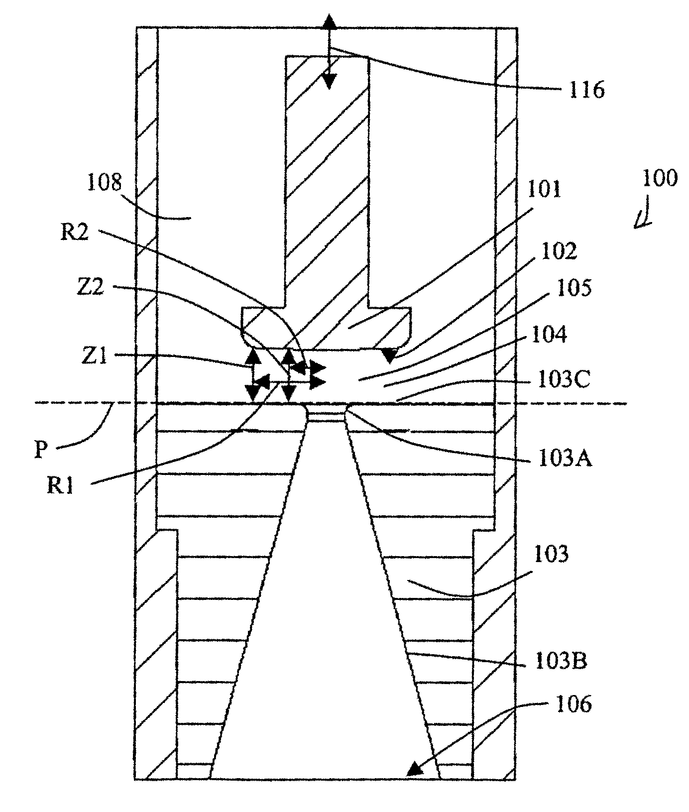
Figure 1 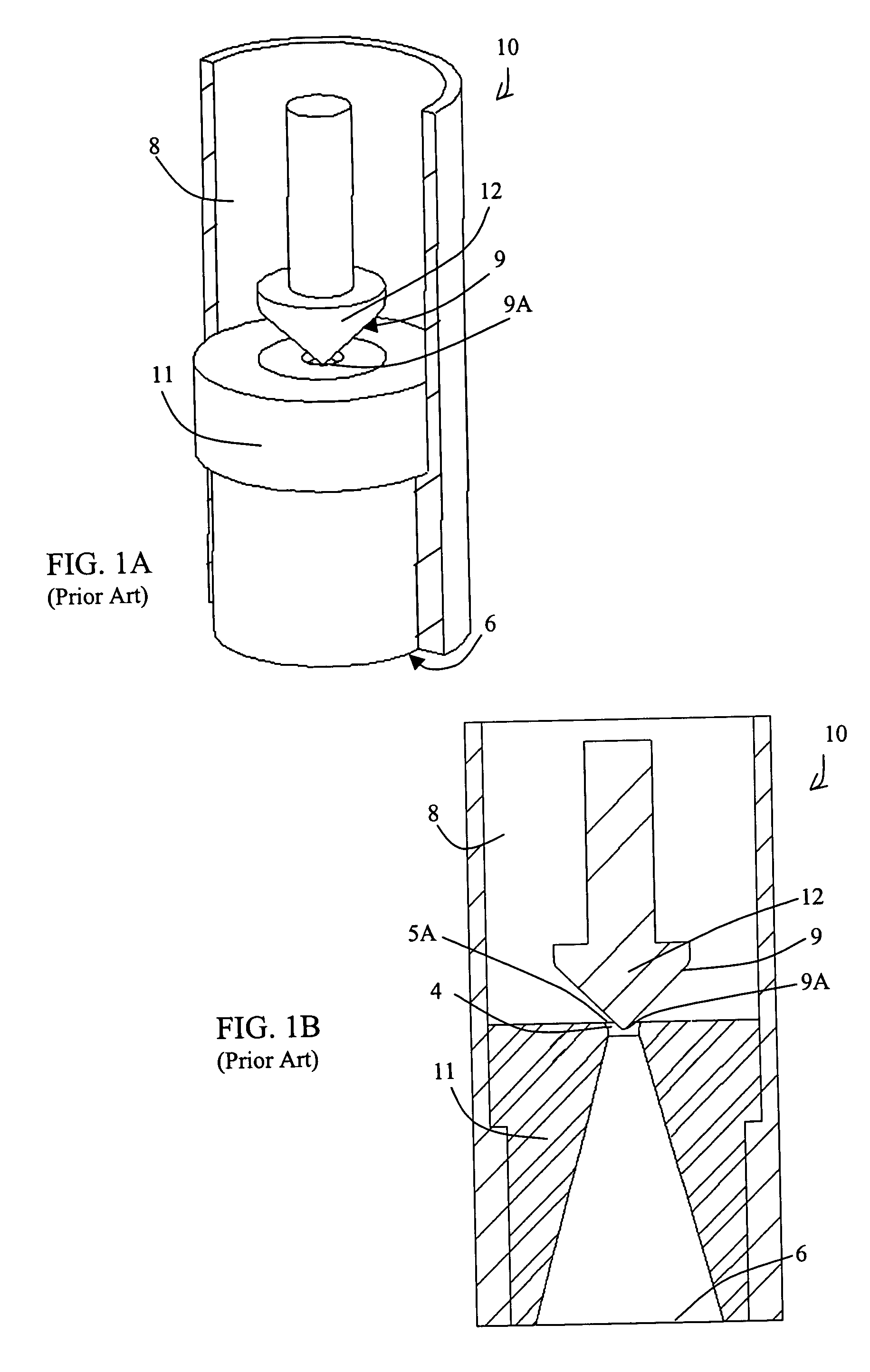
Figure 2 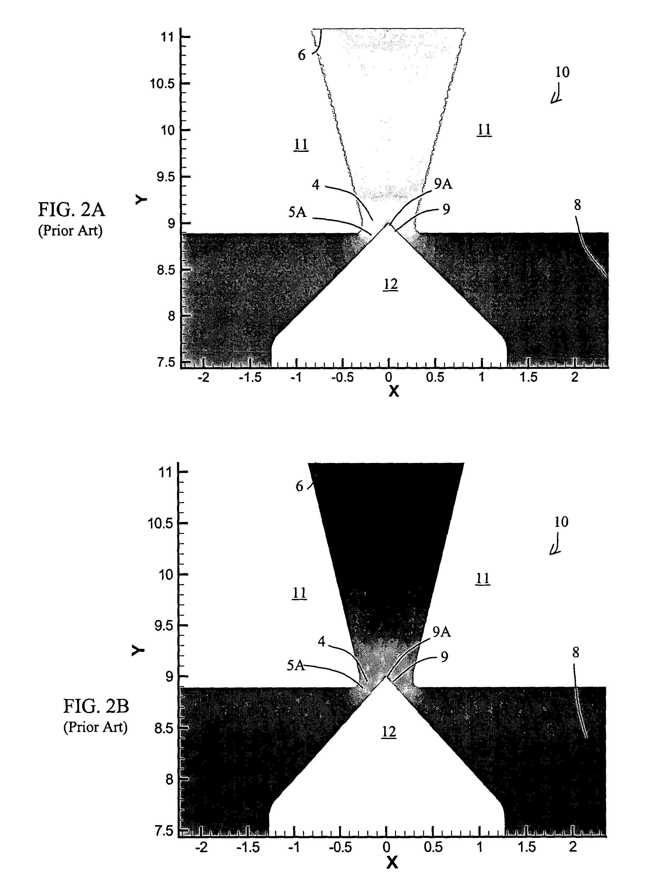
Figure 3
Abstract
Description
[0001] This utility patent application claims priority under 35 U.S.C. 119(e) from application 60 / 413,208, filed on Sep. 24, 2002, the subject matter of which is herein incorporated by reference.BACKGROUND INFORMATION
[0002] 1. Field of the Invention
[0003] The invention relates to the field of fluid control valves. More particularly, the invention relates to fluid control valves for regulating supersonic gas flow.
[0004] 2. Description of the Prior Art
[0005] The purpose of a supersonic flow valve, for example, a thruster valve in a rocket booster or divert thruster, is to align the momentum of fluid flow with the direction of the desired thrust. During optimal performance, all the velocity components of the fluid flow are aligned with the direction of flight or thrust. Vectored flow, that is, flow that has velocity components at an angle relative to the direction of flight, will produce a vectored thrust. Also, if the flow is not properly aligned and turbulence or flow separation occurs, t...
Examples
Embodiment Construction
[0044]The computational flow dynamic (CFD) illustrations submitted with this application are color graphs, whereby the various temperatures, pressures, and Mach conditions are indicated by colors and color gradations. In all illustrations, the highest values are indicated by the color red and the lowest values by the color blue. A normal shock wave is generally indicated by the color yellow.
[0045]FIGS. 1A and 1B illustrate a traditional 45-degree valve 10 with a nozzle 11, a 45-degree pintle 12, a valve plenum 8. The valve is traditionally set into a housing which locates the nozzle and pintle into position. The nozzle 11 has an upper surface 11A, a nozzle inlet 4 and a nozzle exit 6, and the pintle 12 has a tip 9A. The portion of the pintle 12 that extends into the fluid flow provides a fluid control surface 9 that redirects the flow direction toward the nozzle exit 6. A fluid dynamic throat 5A forms between the nozzle inlet 4 and the pintle 12 as the valve 10 opens.
[0046]FIG. 2A a...